"Have you built a KSA50 with those sinks yet? Are you planning to use two per channel. I'm not sure that one per channel will handle it. I used similar sized sinks on my second amp and they had twice the number of fins and I definitely need to run a fan."
I was going to use one heat sink per output board.
I was going to make 2 heat sinked mono blocks or 4 heat sinked stereo version.
Now I am using a slightly different heat sink type in a pre-fabed chassis.
Troy
I was going to use one heat sink per output board.
I was going to make 2 heat sinked mono blocks or 4 heat sinked stereo version.
Now I am using a slightly different heat sink type in a pre-fabed chassis.
Troy
Capacitance
Troy, I'll take those 12 resistors.....just email me with a total and I will paypal you right away....thanks!
Robert
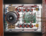
The caps in the picture are actually only 22,000mfd each. Since then I have switched to two 47,000mfd per channel in a CRC configuration with independent bridge rectifiers to make more room in the case.pinkmouse said:Very nice case Robert. How much capacitance are you using?
Troy, I'll take those 12 resistors.....just email me with a total and I will paypal you right away....thanks!
Robert
Does anyone have some spare pinkmouse output boards laying around? I am in the market for 4 more. Send me an e-mail through the thread.
Thanks,
Brad
Thanks,
Brad
Fellow builders
Does anybody of you know what the voltage is running through capacitors 102 & 103 (series elco's). Already looked in the wiki page but without any luck. Maybe it's being asked before but considering the length of the thread......
Regards
Does anybody of you know what the voltage is running through capacitors 102 & 103 (series elco's). Already looked in the wiki page but without any luck. Maybe it's being asked before but considering the length of the thread......
Regards
c102
Hi,
I don't have the schematic in front of me, are c102, c103 the back to back electrolytics?
If they are, the voltage across them is low, except under conditions of gross low freq overload, at which point conceivably you might see a large fraction of the output voltage.
Stuart
Hi,
I don't have the schematic in front of me, are c102, c103 the back to back electrolytics?
If they are, the voltage across them is low, except under conditions of gross low freq overload, at which point conceivably you might see a large fraction of the output voltage.
Stuart
I don't have the schematic in front of me, are c102, c103 the back to back electrolytics?
Yep
Reason of my question is that I want to replace them with a single Non-Polar Black Gate, but the ones I have are rated at 16V.
Regards
Jacco had this to say about the c102/103 voltage back in the 3800's
jacco vermeulen said:
With 25 volts on the output, voltage on the base of Q101/Q102 is again 1.6 volts.
Anything above 1.6 volts will take current from the input stage to make the output voltage drop.
The 23.4 volts difference is the voltage drop over the feedback resistor R130.
The feedback operates so fast there will be very little AC variation between input voltage and voltage on the base of the current mirror.
Under normal operating conditions, even 6.3 volt capacitors would work fine for C102/103.
At switch-on, when the circuitry needs a moment to settle, or during adjusting, there is a possibility of having DC voltage on the output that can raise the voltage on C102/C103.
Charging time for a capacitor through a resistor is 5*R*C.
With R130 at 22K, R129 at 1.5K, and C102/103 at 1000uF , charging time is pretty long.
Means there is not a risk of getting too much voltage on those C's at switch-on.
Only in the event that something is out of wack, or in case of a partially blown output, the voltage rating of C102 or 103 is an issue.
Given price difference of 16 and 50 volt caps i would choose the higher voltage one.
If you do not mind exchanging them after a crash they need not be altered, or you could go for caps with the lowest voltage rating instead of 16 volt specimens.
should be fine...
If you are very worried, you can use a pair of zeners back to back across the cap to protect them from too high a voltage...
a pair of 14v zeners would clamp the voltage to approx. 15v
Stuart
If you are very worried, you can use a pair of zeners back to back across the cap to protect them from too high a voltage...
a pair of 14v zeners would clamp the voltage to approx. 15v
Stuart
Hi,
I have fully finished one of the monoblocks, and fired it up (wearing protective gear of course 😀 ). I followed the steps for biasing on the wiki, after I made sure everything was in order, and everything worked perfectly.
As for the grounding, I took Pinkmouse's advice to first fire up the amp and see if anything is amiss with the grounding. With the input shorted, there was no noise or hum whatsoever coming from the test speaker, so I am assuming that everything is ok with the grounds. I greatly appreciate all of your help, and for my next 2 KSA-50, I will definitely apply the better grounding scheme you guys suggested.
Now, time to finish the second monoblock so I can finally hear them sing.
Paul
Yup, those are Conrad heat sinks (MF35-75).
For the case, I drilled the heat sinks, tapped the holes, and then the front. back, top and bottom are screwed to the heat sink's base. The top and bottom are aluminum pieces from old telecom base-stations panels, and the front and back panels were done by Front Panel Express.
Paul
For the case, I drilled the heat sinks, tapped the holes, and then the front. back, top and bottom are screwed to the heat sink's base. The top and bottom are aluminum pieces from old telecom base-stations panels, and the front and back panels were done by Front Panel Express.
Paul
Hi Joey,
the nfb is connected between the driver board and the voltamp board.
Instead take the nfb from the output rail to the voltamp board and remove the FB link.
Referring again to your pic, I cannot see a link from the output side of the driver board FB to the output rail. Is it hidden or omitted or am I blind?
So, you need two FB links from the output rail, one to the driver board and a second one to the voltamp board.
Those conrads look adequate, can you confirm output Iq and sink temperature?
You're pretty tidy with the wiring and neat layout. Can I assume you deliberately chose to separate the mains incomer from the input RCA? is that coax or plain on the RCA? Could you measure the mVac at the output with the input shorted and open circuit?
Hi Andrew,
The link between the output rail and driver board FB passes under the PCBs, but you can see it emerging right at the positive output terminal (it's the little red wire). So I have a little wire link between the main board and driver board, and then another link to the output from the driver board.
With and Iq of about 588mA per device, the heat sinks seem ok; with the amp running for about 20 minutes without any input, I am able to touch both heat sinks without any pain, but it's not far from it, so I'm estimating the temp to about 45-50C. I'll try to get a more accurate value tonight.
Thanks. Yes, I tried to keep the incoming AC far from the input. From the RCA connector to the main board input, there are two plain silver wires.
As for the mVac at the output, with the input shorted, I get 0.4 mVac, and with it open, I get 2 mVac. When I checked the Vdc, I got 8 mVdc with it shorted, and 207 mVdc with it open. Is that normal?
Thanks
Paul
Referring again to your pic, I cannot see a link from the output side of the driver board FB to the output rail.
The link between the output rail and driver board FB passes under the PCBs, but you can see it emerging right at the positive output terminal (it's the little red wire). So I have a little wire link between the main board and driver board, and then another link to the output from the driver board.
Those conrads look adequate, can you confirm output Iq and sink temperature?
With and Iq of about 588mA per device, the heat sinks seem ok; with the amp running for about 20 minutes without any input, I am able to touch both heat sinks without any pain, but it's not far from it, so I'm estimating the temp to about 45-50C. I'll try to get a more accurate value tonight.
You're pretty tidy with the wiring and neat layout. Can I assume you deliberately chose to separate the mains incomer from the input RCA? is that coax or plain on the RCA? Could you measure the mVac at the output with the input shorted and open circuit?
Thanks. Yes, I tried to keep the incoming AC far from the input. From the RCA connector to the main board input, there are two plain silver wires.
As for the mVac at the output, with the input shorted, I get 0.4 mVac, and with it open, I get 2 mVac. When I checked the Vdc, I got 8 mVdc with it shorted, and 207 mVdc with it open. Is that normal?
Thanks
Paul
Thanks Joey,
that 207mVdc output offset when input is open may be a problem when using a DC blocked output from a pre-amp.
The KSA will see an open circuit due to the cap at the output and leave you with that offset.
Do any others have similar readings?
It may be that once you have the system connected up that you zero out the offset with the pre-amp connected.
That 0.4mV is -94db relative to full power. I was hoping it would be better. Is this normal?
Paul, twist both input wires together ( at full fart ) .... 😎 - now is area of input loop too large and it capture hum...
- Home
- Amplifiers
- Solid State
- Krell KSA 50 PCB