Mark A. Gulbrandsen said:It turns out that this transformer is a 1.240 kva unit...
Mark
Don't I feel real stupid....! I already had a couple of 1kva's lying around...
 , Go ahead Jacco, laugh your @$$ off.
Mark is your 1250va based on the schematic's 80C rise at that level?
Mark is your 1250va based on the schematic's 80C rise at that level?
Yes, I believe that is correct since you need to go by the rating at the specified rise temp.
Jeno,
Go back a few pages as there is a link to the transformer. I think its www.audiohobby.com but I'm not absolutely sure.....
Mark
Thanks Mark
Yes I found it .I already sent a message but looks like he does't shippe to Canada .
Let see .
Thanks any way.
Yes I found it .I already sent a message but looks like he does't shippe to Canada .
Let see .
Thanks any way.
Googler, those are very nice! So lets see if they are sufficient.....oh wait, I don't see your amp on the Krell-O-Tracker in the Build Wiki, so we don't know how many outputs, rail voltage, etc..... I've added it so go ahead and enter the particulars.
People, keep that thing updated! There must be 20 people with amps planned that didn't enter it into the tracker.
K-Amps looks like its you and me who read that thing.
Hey, K-Amps, looks like you are now calling this the-
"Krell Klone KSA-50/ KSA-500 build instructions / Wiki."
KSA-500????
Man Stuart better give a major update!
I just updated mine a couple of hours ago. Since I have a toroid from Bel Canto in it can I call mine the Krell Canto..... . With the number of boards I've shipped out in the last year there are alot of people out there that need to post what they are building!!!
Lets not let those pesky little Pass JFET amps Pass us up in sheer quantity....
Mark
. With the number of boards I've shipped out in the last year there are alot of people out there that need to post what they are building!!!Lets not let those pesky little Pass JFET amps Pass us up in sheer quantity....
Mark
lgreen said:Googler, those are very nice! So lets see if they are sufficient.....oh wait, I don't see your amp on the Krell-O-Tracker in the Build Wiki, so we don't know how many outputs, rail voltage, etc..... I've added it so go ahead and enter the particulars.
Thanks lgreen. I thought I had put my info in there at one point, I guess I didn't 😱
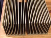
The sinks are 12x5x5 ribbed fins. I have the heatsink calc spreadsheet, it doesn't account for ribs or for fin shape. I believe the assumption of the calculations are that the fins have a triangular profile - which my logic leads me to believe would disperse heat a bit more evenly than the "flat" fins that I have. Lots of math to take in to account- I may just hook it up and monitor temperature as I raise bias to determine if they can take the heat.
~Brad
K-amps said:Go ahead
Arif,
my @$$ is still hurting from the box of flat belts that MCM Newark sent me de-routed through Canada, and the bogus batch of Motorola TO3s i bought.
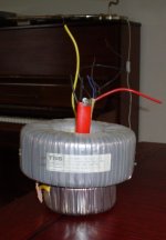
On the other hand,
here's a pic of one of four 1.8KVA toroids i collected for a Pass clone. Dual secondaries, 36Vac, 25 amps. Made for ship to shore powersupplies, overhere anything above 1 KVA is custom order and pricy.
www.Victronenergy.com
Also managed to collect 4 of their 3.6KVA 115 to 230 toroid isolation transformers when the Pass Monster thread started. Still need to figure out what i'll do with the 4 chassis, they are huge. Older series, weigh 120lbs each, cost me $200 for all 4. I just love hauling junk with my Chevy.

www.victronenergy.com/upload/documents/Datasheet-UK-Isolationtransformer.pdf
Mr Green, coming sunday i'll be waving at the 2006 Amsterdam boat show !
Boaties rule !

Attachments
Hi Googler,
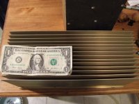
You mentioned cutting the sinks in half to give 6*5*5.
If you stack them side by side giving 6*10*5 they will dissapate about 40% more heat than uncut.
10inch on opposite sides of a case should leave room to build your 2channel inside.
Someone was asking about transistor placement for best efficiency.
If one only, place it in the middle but drop it down slightly below centre line. i.e. about 40 to 45% up from the bottom.
If placing two or more side by side then again 40% up from bottom but the spacing should try to ensure that the side to side gaps to edge and to the midpoint between TRs should be equal i.e. for 3TRs 17% from edge then 33% to next & 33% to third and finally 17% to edge.
If placing two or more rows stacked above each other, then the spacing becomes a little more complicated.
Basically the problem you are trying to overcome is that warm air passing up through the lower part of the sink does not cool the upper part of the sink as well. So this forces the upper sink to run hotter than the lower. To compensate for this the upper row of TRs need extra area compared to the lower rows.
I suggest you try for 20% to 25% up for lowest row, 40% up for middle row and 65% for third row
Thanks Andrew!
One thing is for certain, I have plenty of transistors on hand to try different configurations.
Is the up from bottom placement meaning the bottom, midpoint, or top of the TR case is 40% up from the bottom?
I assume for side to side placement, to leave 17% from the edge of the sink to the side of the TR...
I definately will be cutting the sinks to make 6*10*5 arrangement like you mentioned.
Thanks,
Brad
googler said:Does the fact that it is Class B rated account for the 750VA discrepency ? Class B is 130C ?
I sure hope so.... Any more code certified types please confirm:
lgreen said:Googler, those are very nice! So lets see if they are sufficient.....oh wait, I don't see your amp on the Krell-O-Tracker in the Build Wiki, so we don't know how many outputs, rail voltage, etc..... I've added it so go ahead and enter the particulars.
People, keep that thing updated! There must be 20 people with amps planned that didn't enter it into the tracker.
K-Amps looks like its you and me who read that thing.
Hey, K-Amps, looks like you are now calling this the-
"Krell Klone KSA-50/ KSA-500 build instructions / Wiki."
KSA-500????
Man Stuart better give a major update!
Stuart, Where art thou oh Stuart.
Any chance you have the time to compile your notes in one place on measurements/ mods etc.
thanks.

Hi Googler,
I would suggest that you assume it to be geometric centre. But almost as accurate (sufficiently accurate) would be the tapped fixing hole locations. Just scribe out your layout, drill, tap and then fix in position.
Reminder:- the baseplate thickness fixes the maximum spread of heat along the sink. Efficient spread <=10 times thickness. Similarly for fin thickness :- fin height (at right angles to plane of base plate) <=10 times fin root thickness and fin taper should be less than 3 to 1. So your 4.5inch high fins should be 0.45 thick at the root or you lose some efficiency. I don't know how much (you were about to ask weren't you?).
AndrewT said:I don't know how much (you were about to ask weren't you?).
How did you know? 😀
I will have to measure the base plate thickness tonight when I get home. If it is less than .45inches, would I be better off using more transistors to distribute heat accross the base?
This also brings up another question - Does increasing the number of output transistors require changing the emiiter resistor values?
Thanks,
Brad
- Home
- Amplifiers
- Solid State
- Krell KSA 50 PCB