K-amps said:All I wanted to do was recoup the cost... BUT, look what they sold for.... What do I do with the extra cash? I don't feel comfy keeping it...Donate to DIYaudio? 😀
Well, I won't say we don't need the cash, 'cos we do. 🙂
But if you really made $300, then I think there are a couple of people that deserve a bottle of wine or box of chocolates in our own little cloning gang, i.e. Jan, who got us going to start with, and Troy, who's been sweating over the component kits for the last 6 months. 😉
No doubt, you , Troy, Mark and Jan deserve it... but I cannot put a price on your efforts 😀 Al, gimmie the DIYaudio paypal account, I will send some there. Rest to recoup expenses/ gas/ fees etc.
K-Manic.
K-Manic.
Not spotted the "Make a Donation" button at the top of every screen? I guess we'll have to make it bigger! 🙂

jacco vermeulen said:
Say what ?
All with empty boards: Sell, Sell, Sell !!
Hey, don't give Mark any ideas. There are still lots of DIY'ers who need to build one of these amps.
Blessings, Terry
What is the purpose of the optional 2 ohm base resistors for the output devices?
I understand their use for Mosftes but have not seen them used for output transistors.
Also why were the feedback resistor values changed from the original circuits?
I understand their use for Mosftes but have not seen them used for output transistors.
Also why were the feedback resistor values changed from the original circuits?
I like mine just the way they are, thank you....All with empty boards: Sell, Sell, Sell !!

base resistors
The idea behind the base resistors was to 'help' current sharing between the output transistors. I believe they will have little or in extreme cases the opposite effect, if current sharing is a major concern increasing the emitter resistors is the way to go. In the 5 boards I've assembled so far including one amp with 20 outputs the sharing was always within 5%, ie limited by the tolerance of the emitter resistors...I didn't match any transistors, and since many were donated there was little or no chance they came from the same 'batch'.
Not sure why the feedback resistor values would have 'changed', they are not critical, as long as the ratio remains reasonably constant, and it is likely a more readily available pair of values was chosen. Depending on which variant of the board you are assembling you would need to ask different people...probably Pinkmouse...
HTH
Stuart
Hi,
I agree with Stuart, to help with current sharing and as he said a smaller effect than Re.
Base resistors also aid stability by damping oscillation.
Finally, they reduce peak current in event of overload. This may save an amp from destruction.
I agree with Stuart, to help with current sharing and as he said a smaller effect than Re.
Base resistors also aid stability by damping oscillation.
Finally, they reduce peak current in event of overload. This may save an amp from destruction.
Am back home and I believe I answered everyones e-mail about boards. If I left someone out please accept my appologies and nudge me again.
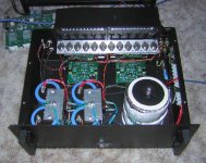
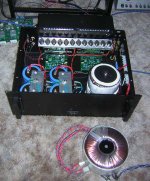
On a different note here is a photo of the insides of my finished KSA-50 Klone..... Some may cringe at the common TO-3 mounting rail..... but so far so good. Thermal tracking with the dual fans running is actually quite good.
Mark
On a different note here is a photo of the insides of my finished KSA-50 Klone..... Some may cringe at the common TO-3 mounting rail..... but so far so good. Thermal tracking with the dual fans running is actually quite good.
Mark
Attachments
Mark,
very clever to place the vented duct behind the chassis. This corner still is a great source for ideas.
I cringe at the sight of a finished chassis.
very clever to place the vented duct behind the chassis. This corner still is a great source for ideas.
I cringe at the sight of a finished chassis.
 Great work Mark. Nice wiring/ finishing.
😱 That looks much more than a 50 watter!
 Why Can't I get a Toroid like that!!
Mark A. Gulbrandsen said:The stacked 400 VA trannies will be replaced by this massive(surplus) Bel-Canto 2KVA tranny...hopefully this week.
Mark
I got my 2kva tranny in as well. Are you planning on leaving the the stock connectors on yours?
I haven't decided whether to buy the female connectors to plug in or snip off the stock ones and solder directly.
Is that power switch on the front functional?

Bad Boy! Never send that link to a Toroid Junkie.... 
Hey Jacco, Look what I am getting.
😀 TY Googly!
Hey Jacco, Look what I am getting.
😀 TY Googly!
I got my 2kva tranny in as well. Are you planning on leaving the the stock connectors on yours?
I will cut mine off and use my typical Crimp on female spade lugs, (I also solder them as well) that slide directly onto the tabs of the bridge rectifier. I use a central grounding point between the two main caps as my star ground point and the center taps are placed there. Its a VERY nuce toroid... easily a $300.00 tranny. I think they were made by Toroid Corp Of Maryland.
I wonder what happened to Bel-Canto?
Mark
- Home
- Amplifiers
- Solid State
- Krell KSA 50 PCB