sorry
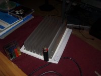
Sorry. those heatsinks are very thick and the transistors face opposite each other, so they twisted when it was installed. After months of looking it was the only heat sink I could find with two smooth sides suitable for mounting opposite facing transistors. Can't do anything about it now but they should run cool and live long.
I did file the edge- you should have seen it before! guess I should sand it to make everyone happy.
Tekko said:The heatsinks are not in alignment with the boards, that is what is bugging me. I like it when both transistors live on the same side of the heatsink and when its paralell with the board. Yes i can see you cut the heatsink with a hacksaw, you want to file those ends to make them look nice again.
Sorry. those heatsinks are very thick and the transistors face opposite each other, so they twisted when it was installed. After months of looking it was the only heat sink I could find with two smooth sides suitable for mounting opposite facing transistors. Can't do anything about it now but they should run cool and live long.
I did file the edge- you should have seen it before! guess I should sand it to make everyone happy.
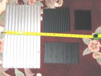

kmj said:Will one of these/channel do or are they to small?
Are you planning on using them external or face to face with a couple of fans on them. If you use them externally they should be mounted with the fins running vertically. I think you can lay them horizontally if you stick a couple of fans one one end.
Others know more than me though. I think a couple of the folks here are using sinks like that with fans. Maybe they can chime in.
Blessings, Terry
I thought that i could use them externally and use them as the shortsides of the chassi (horisontally) and them add some fans inside to make an airflow.
but perhaps it's best to buy a pair of them tunnels from apexjr instead
but perhaps it's best to buy a pair of them tunnels from apexjr instead
Cooling
So far everyone seems to be using forced cooling. Has anyone had any success with stand alone heat sinks without fans, or is this not possible with the heat generated? If anyone has had success, what size and rating of heat sink has been used?
Jacco, I think mentioned earlier in this thread that the original Krell had a Papst fan 4800X for cooling. UK online deals catalogue (http://www.ukonlinedeals.co.uk/acatalog/Hardware.html) are doing a good deal on Papst 4850N which seems to be a very near equivalent.
There was also some talk of a getting the fan to attenuate with respect to the heatsink temperature. Again, Papst do a range called Variofan that has a remote temperature sensor that continuously varies the fan speed between 25-50 degC but requires 12V DC (noise varies between 22 and 39 dB(A) for their lowest rated variopfan. Could this be another option?
What is wisdom ?
Personally i hate these pesky little resistors with 0.16" body, like the ones Yageo makes.
Like with transistors, i'd settle for a 1/4 watt resistor if it only has a 1/8 watt load.
Especially with class A amplifiers surrounding temperature of resistors can be a lot higher than test temperature.
Dale used to mark the resistors for the value they'd handle at temperatures that can be realistic.
No need to have like a 50 % safety margin in case of higher temperatures.
Means if the load is around 1/4 watt i'd go for the one that does 1/2 watt under the new Vishay regime.
8.50 certainly is a good offer, Mr Barnez.
Without a fan you'd have to use around 3 times more cooling surface.
At 1.8 amps bias for 50 watts class A, 37.5 volts rails, dissipation is 135 watts.
You'd need a 0.20 C/W heatsink per channel, think big.
Thanks Jacco,
What about those Variofans? Could they be incorporated? If so noise could be kept down at low listening levels.
Has anyone tried the heatsink tunnels from ApexJR? They seem good value, but postage is likely to be costly to Europe?
Anyone know the weight for a pair of them, or otherwise anyone know where to get an equivalent in England/Europe?
Bud Barnez said:Thanks Jacco,
What about those Variofans? Could they be incorporated? If so noise could be kept down at low listening levels.
Has anyone tried the heatsink tunnels from ApexJR? They seem good value, but postage is likely to be costly to Europe?
Anyone know the weight for a pair of them, or otherwise anyone know where to get an equivalent in England/Europe?
Hey Bud,
I use 3 x 8cm 38db fans, running @ 8v (instead of 12v) and they run quiet enough that i can't hear them even in quietest passages... If EVERYTHING is silent, i can hear them.... But i don't worry much, if i did, i'd get quieter fans 🙂
I'm using 0.25c/w heatsinks (2 of them) together to form a tunnell, using 3 fans - i am dissapating about 300w/channel (not sure on exact measurements, but its' about that!) so that's 600w from 2 x 0.25c/w with 3 fans...... without them (fans) i can dissapate about 70w or so i think....(per heatsink)... that's why fans are a "must"...
Aaron
Hi guys,
Well I have a new problem. Last night when I switched on my system I heard a buzzing sound coming from the speakers. Not a low hum but more of a buzzing sound. After checking things a bit I unplugged the inputs to the Krell and that stopped it. I tried plugging stuff into different outlets and the like to no avail. As long as nothing is plugged into the inputs there is no hum/buzz. It’s not really loud but it’s there. So I pull the cover off and start checking things out. The RCA jacks are not isolated from the case so I’m thinking maybe I’m getting a ground loop so I pull the jacks out of the case. By the way, I added a separate ground wire to the PCBs by attaching it to a wide spot on the ground trace. I had run these wires to the star ground and only connected the ground from the RCA jack to the ground terminal next to the input on the PCB.
Anyway, pulling the input jacks out of the case and just letting them hang lessened the buzz but didn’t kill it. So I took the nut off of the star ground so I could remove ground wires one at a time to see if I could get rid of the buzz. What I found was that removing the extra PCB ground wires from the star stopped the buzz as long as the RCA jacks were grounded to the case. So right now I have those extra wires removed. I’m not sure I like this since the ground for the PCB is now running through the ground wire for the RCA jack and through the case, but there is no buzz.
Now for my real problem. While testing for the ground problem, the center tap wires got removed from the star ground for a second while the amp was on. I heard a sizzle sound and I hit the off button. I hooked things back up and turned the amp back on. It seems to play fine but now when I shut the amp off, I hear a hissing or sizzling sound for a couple of seconds after I hit the switch. It didn’t do this before so I’m thinking I hurt something. Any Ideas as to what I may have damaged by running it without the CT attached?
Thanks, Terry
I can't tell where the sizzles came from. Were they coming out of the speakers or from the amp itself?
If you reconnect the wires and bring back the buzz, do they go away?
If you reconnect the wires and bring back the buzz, do they go away?
caps...
There is some chance the voltage across one or more of the electrolytic caps reached too high a level, in the event one of them is 'damaged' and venting you would hear noise.
Assuming you have spares, I'd replace them and look for evidence of failure in the removed items...
HTH
Stuart
There is some chance the voltage across one or more of the electrolytic caps reached too high a level, in the event one of them is 'damaged' and venting you would hear noise.
Assuming you have spares, I'd replace them and look for evidence of failure in the removed items...
HTH
Stuart
Re: caps...
Stuart did you ever finalize your design for 100-105v rails?
😀
Stuart Easson said:There is some chance the voltage across one or more of the electrolytic caps reached too high a level, in the event one of them is 'damaged' and venting you would hear noise.
Assuming you have spares, I'd replace them and look for evidence of failure in the removed items...
HTH
Stuart
Stuart did you ever finalize your design for 100-105v rails?
😀
yes...
...up to the 800w RMS into 4r mark. What this means is I started with 105v rails, but under full power into 4ohms, the rails sagged to approx. 85v. For the next test I have a PSU with twice the capacity (2.8kva), being fed from a 240v spur from the dryer plug, so rails sagging are a bit less of an issue...
I am still in process of remaking the output stage using higher value Re, but I can post a list of changes, I'd be very interested in someone else making the thing to test if it really is repeatable. I'd do it, but I don't have the components required, and since I don't plan on keeping the amp intact once it's 'proven', I am not going to buy them.
I'll compile the list of changes, then put them on the Wiki, at which point I'll post here to let you know...
HTH
Stuart
Re: yes...
thanks... as soon as the boards arrive to me... I'm following in your footsteps so I'll keep it up to date
as far as 240v from a wall... that's not possible with me... but I'm not too interested in pushing the 800 watts into 4r
more interested in 500 watts in 4r biased for 100watts of Class A😀
Stuart Easson said:...up to the 800w RMS into 4r mark. What this means is I started with 105v rails, but under full power into 4ohms, the rails sagged to approx. 85v. For the next test I have a PSU with twice the capacity (2.8kva), being fed from a 240v spur from the dryer plug, so rails sagging are a bit less of an issue...
I am still in process of remaking the output stage using higher value Re, but I can post a list of changes, I'd be very interested in someone else making the thing to test if it really is repeatable. I'd do it, but I don't have the components required, and since I don't plan on keeping the amp intact once it's 'proven', I am not going to buy them.
I'll compile the list of changes, then put them on the Wiki, at which point I'll post here to let you know...
HTH
Stuart
thanks... as soon as the boards arrive to me... I'm following in your footsteps so I'll keep it up to date
as far as 240v from a wall... that's not possible with me... but I'm not too interested in pushing the 800 watts into 4r
more interested in 500 watts in 4r biased for 100watts of Class A😀
Hi Stuart,
If by electrolytics you mean the filter caps, I don't think that is it. The sound is coming from the speakers. Before, when I would shut of the system there would be silence. Now I hear a slightly distorted pfssst sound that increases for second or so and then dies out quickly. I'll measure the output of the PSU when I get home to see if there is any AC on it. The amp sounds fine when playing AFAICT. I had already closed it all up by the time I heard this and didn't have time to open it up again last night. I will try to do more testing tonight. Does it normally hurt an amp to disconnect the center tap while the power is on? I'm not sure the filter caps would see anything differently since I have many times hooked up filter caps to a transformer so I could take measurements. The amp however would only have voltage on the rails and no CT return. Maybe that doesn't matter, that's why I'm asking. Like I said earlier, the center tap is only connected to the PCBs through the ground wire to the RCA jack which is grounded to the case. I've got to get that sorted out too.
Blessings, Terry
Re: yes...
I'm interested in this too. I was thinking about making the new boards into a KSA 100 of sorts since I already have a KSA 50
Blessings, Terry
Stuart Easson said:...up to the 800w RMS into 4r mark. What this means is I started with 105v rails, but under full power into 4ohms, the rails sagged to approx. 85v. For the next test I have a PSU with twice the capacity (2.8kva), being fed from a 240v spur from the dryer plug, so rails sagging are a bit less of an issue...
I am still in process of remaking the output stage using higher value Re, but I can post a list of changes, I'd be very interested in someone else making the thing to test if it really is repeatable. I'd do it, but I don't have the components required, and since I don't plan on keeping the amp intact once it's 'proven', I am not going to buy them.
I'll compile the list of changes, then put them on the Wiki, at which point I'll post here to let you know...
HTH
Stuart
I'm interested in this too. I was thinking about making the new boards into a KSA 100 of sorts since I already have a KSA 50
Blessings, Terry
Bud Barnez said:What about those Variofans?
Of course, question is whether you wish it.
Variofans operate with a thermistor, for some Papst models you need a separate thermistor, think the part is called an LZ370, costs about 1 pound
imo, part of the class A magic is its thermal stability.
With a fan that constantly changes its rev., temperature of the sink changes constantly too.
Thus behaving sort of like a class AB amplifier.
Question also is whether variofans are on offer, old series Papst vents can often be had brandnew for a few shillings and pence.
More elegant would be to switch the fans to a higher speed from a certain temperature upwards through a transistor that is driven by a thermistor mounted on the heatsink, be it NTC or PTC.
http://www.overclockers.com.au/techstuff/a_thermalfans/
I just bypass the resistors that derate the fans i am using with a thermal switch, screwed on the heatsink duct.
I'm interested in this too.
Amphetamines? NO, i am on Amps.

- Home
- Amplifiers
- Solid State
- Krell KSA 50 PCB