47 pF capacitor
I really hate to give advice, being that I can't even make ventilation holes in aluminum.....and that I'm not sure if my amp is going to work yet. But given this, if my amp works, i'll try and dig up my parts order, should there be an interest.
For the 47 pF capacitor (c105 and c106), I'm going to use an AVX multilayer film cap, available at Mouser, here. Its on page 593 of the catalog. There are other values on this page if you can't find Wima caps of the right value- Mouser stopped restocking some of these Wima caps I believe so make sure you check and see if any are available should you order from there.
For C102/103 and C110/111 I just used plain old electrolytic capacitors rated at least for what's called for.
For C107/C108 (100pF) I used either AVX or Wima, I forget which. I know I ordered both. Maybe this is the one they didn't have Wima for at the time.
For the .6 Watt resistors I just went ahead and used 1 watt resistors, the rest of the .5 watters I bought vishay/daly CCF series like
this. They kind of claim to be rated for .5 watt, "1/4WATT 47.5KOHMS 1% Rated to 1/2WATT" but also mention .25 watts....now why would they do that if it was for 1/2 watt??? Hey, which is it?? That is why I'm slighly worried, but will try and see.
Hope this works
Firstly, do you definitely have to use Panasonic M-series for C102/3 and C110/1, or will any other produce the same results? For C105/6, I cannot find any Wima FKP2 to buy, except in 500 packages, so is there an alternative to 47pF (way higher)? And for C107/8, once again, do you have to use Evox Rifa PFR5, or are there alternatives?
I really hate to give advice, being that I can't even make ventilation holes in aluminum.....and that I'm not sure if my amp is going to work yet. But given this, if my amp works, i'll try and dig up my parts order, should there be an interest.
For the 47 pF capacitor (c105 and c106), I'm going to use an AVX multilayer film cap, available at Mouser, here. Its on page 593 of the catalog. There are other values on this page if you can't find Wima caps of the right value- Mouser stopped restocking some of these Wima caps I believe so make sure you check and see if any are available should you order from there.
For C102/103 and C110/111 I just used plain old electrolytic capacitors rated at least for what's called for.
For C107/C108 (100pF) I used either AVX or Wima, I forget which. I know I ordered both. Maybe this is the one they didn't have Wima for at the time.
For the .6 Watt resistors I just went ahead and used 1 watt resistors, the rest of the .5 watters I bought vishay/daly CCF series like
this. They kind of claim to be rated for .5 watt, "1/4WATT 47.5KOHMS 1% Rated to 1/2WATT" but also mention .25 watts....now why would they do that if it was for 1/2 watt??? Hey, which is it?? That is why I'm slighly worried, but will try and see.
Hope this works
This is interesting. For C-105, 106 I used the value on Jan's schematic which is 330 pf...... 100 pf for C107, 108. These are surely there to supress any chanace of oscillation and my 1st amp measures and sounds great, 1 khz and 10 khz square wave also looks really clean..... whats up with all these small values that everyone is now using.... won't there be a tendency for amps with the smaller values to oscillate?
Mark
Mark
C106
That is exactly why I asked the question in Post 2437. I put citations to some related posts (the ones I know of) into the build wiki, so if you want to see more, check there.
This is interesting. For C-105, 106 I used the value on Jan's schematic which is 330 pf...... 100 pf for C107, 108. These are surely there to supress any chanace of oscillation and my 1st amp measures and sounds great, 1 khz and 10 khz square wave also looks really clean..... whats up with all these small values that everyone is now using.... won't there be a tendency for amps with the smaller values to oscillate?
Mark
That is exactly why I asked the question in Post 2437. I put citations to some related posts (the ones I know of) into the build wiki, so if you want to see more, check there.
Value of C105/106 have big impact at distortion by high frequecies. It must be small as possible. 😉
I think your boards will be just fine at standard rail voltage.. I reccomend running JUST the driver board without the outputs in place first to check its operation. This could save a set of outputs if somthing is wired wrong. You can still check and adjust the bias and check the DC balance adjstment for proper operation first. Better to be safe than sorry. Again, the only resistors you may want to be concerned about are the ones I mentioned above. Also, just so you know, the bias pot works backwards... you turn it down(counter clockwise) to increase the bias current and so on...... the drivers temp will also increaase with increased bias current.
Well, my first one has very low distortion and very clean square wave. These are supposedly the original KSA-50 MK-2 values for these parts....... Going too small will also make the amp more suseptable to oscillation and or sensitive to local RF interference. I guess we need to see an ooriginal KSA-50 mk-2 to be sure what they reallly are.
Mark
Value of C105/106 have big impact at distortion by high frequecies. It must be small as possible.
Well, my first one has very low distortion and very clean square wave. These are supposedly the original KSA-50 MK-2 values for these parts....... Going too small will also make the amp more suseptable to oscillation and or sensitive to local RF interference. I guess we need to see an ooriginal KSA-50 mk-2 to be sure what they reallly are.
Mark
vAD,
No offense at all taken! We are building these Krell clones because it is a very good but practical to construct class A power amp. IT PERFORMS EXTREMELY WELL!! This amp is still being used as a refrence amp by a number of high end audio magazine reviewers today. Sure there are other high end amps to build clones of but this is a very good place to start.
And besides, it's more fun to make something that isn't that wide spread unlike a gainclone (done that) or a PASS-product. 🙂
"... very low distortion ... " - do you have some objective measurement ? Square wave tell nothing about distortion 😉 .
Al, while we are at it :
what trace width and hole size did you select for Q105/Q106 ?
I'd like to know if i can squeeze in original TO220 legs instead of TO92 mpsa's, or have the space on the traces to drill the holes a bit wider.
what trace width and hole size did you select for Q105/Q106 ?
I'd like to know if i can squeeze in original TO220 legs instead of TO92 mpsa's, or have the space on the traces to drill the holes a bit wider.
Krell-O-Tracker Added to Wiki
I've added a Krell-O-Tracker as an Appendix to the Krell Build Wiki.
My hope was that as people complete their projects they fill in the basics of what they have done. I've filled in the "original" part for the standard krell given what is on the wiki.
I guess that there are only 2 complete now, so it kind of depends on them as to whether or not to contribute to this...if there is disagreement or editing to be done, feel free to delete or edit this part of the wiki.
I'll post a gainclone one too, it would be interesting to see how many of those have been built.
"... very low distortion ... " - do you have some objective measurement ? Square wave tell nothing about distortion .
Yess, I have a Sound Technology 1701A distortion analyzer. I had made some quickie measurements on my first KSA build and it was quite good at about .008% average across the band at 10 watts into 8 ohms. Square wave looks square, no rounding of the rise, etc.... so pretty good linearity and a very fast amp. This was with the 330pf and 100 pf values in the amp. I have 680pf on the input.
I am somewhat more curious to see the distortion spectrum... hopefully this weekend time permitting.......
Mark
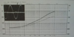
Here is visible quite clear too high compensation capacity, curve rise. With lower compensation it will be much flater 😎 .
Only kidding, Pavel, not disagreeing.
You've been guiding the KSA design since post 21, every gain device from the original design has been altered.
Change the compensation C's and we may better call it a Pavel Stereo Amplifier, the Krell PSA50. 😀
If you take the Threshold Stasis amplifiers from those years, those had nearly constant distortion, almost to 20KHz.
The amplifiers by Mr Pass were the first i saw that had a gradually decreasing harmonics spectrum, with lower uneven harmonics. (NP> clever dicky)
Why Mr D. placed 390pF in the posted original circuit is a mystery.
What is your advice on the accuracy of those capacitors ?
Every amps with similar curves, which I had heard ( and belive me, I had heard realy many amps ), had " unpleasant " trebles, including NP's " modernst " ones, where is this curve typical. Some manufacturers call it as " musical " amp, but I hear it like distortion and I don't take it. 😎
- Home
- Amplifiers
- Solid State
- Krell KSA 50 PCB