If anyone is looking for a set of boards I still have two pair left from the original run that I won't be using. Just let me know.
Mark
Mark
hi pierre (PWatts).
were you able to make the PCB-files available for us?
would be so nice if we can get them.
thx.
regards
slavko
were you able to make the PCB-files available for us?
would be so nice if we can get them.
thx.
regards
slavko
hi.
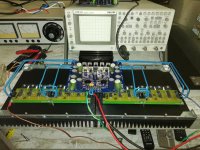
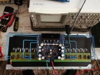
i have a problem with testing my krell clone:
i use 8 x MJE3281a and 8 x MJE1302A for outputs per side (should be biased with 300mA).
Q1, Q2 are 2sc2240
Q3, Q4 are 2SA970
Q9, Q11 are 2SA968
Q10, Q12 are 2SC2238
Q13, Q14, Q16 are MJE15030
Q15 Q17 are MJE15031
when i power up slowly even with 10V DC per rail the bias is raising (>300mA) too high.
i checked everything but i couldn´t find the fault.
did anybody have the same behaviour and can help out?
thank you in advance.
slavko
Is the Vbe multiplier thermally coupled to the output stage?
The KSA100 should be biased to ~2.6A
That gives a maximum ClassA output of ~5Apk and that equates to 100W of ClassA into 8r0 dummy load.
For an 8pair output stage, each pair should be biased to ~325mA +-tolerance, so expect your bias to be >300mA on any single emitter resistor.
The KSA100 should be biased to ~2.6A
That gives a maximum ClassA output of ~5Apk and that equates to 100W of ClassA into 8r0 dummy load.
For an 8pair output stage, each pair should be biased to ~325mA +-tolerance, so expect your bias to be >300mA on any single emitter resistor.
Last edited:
i know that the output should be biased to about 320mA.
but with +/- 10V the bias is already at 300mA with the potentiometer to minimum.
when i power more up the bias will raise to a big value and destroy everything...
but with +/- 10V the bias is already at 300mA with the potentiometer to minimum.
when i power more up the bias will raise to a big value and destroy everything...
thank you andrew.
i really checked everything 10 times.
but i had no luck with finding the problem.
both sides are the same with same behaviour.
regards
slavko
i really checked everything 10 times.
but i had no luck with finding the problem.
both sides are the same with same behaviour.
regards
slavko
if the potentiometer is wired in correctly, then a high value gives a low bias voltage.i know that the output should be biased to about 320mA.
but with +/- 10V the bias is already at 300mA with the potentiometer to minimum.
when i power more up the bias will raise to a big value and destroy everything...
Have you set the bias voltage correctly?
Have you wired in the pot correctly?
a multi-turn with 3 inline pins can be inserted in two different orientations.
Many PCB layout designers can't be bothered to check which way around the pot should be inserted. They leave it down to chance, which leaves the Builder to check the orientation.
Sounds like you did not check.
Many PCB layout designers can't be bothered to check which way around the pot should be inserted. They leave it down to chance, which leaves the Builder to check the orientation.
Sounds like you did not check.
i checked and i think the poti is good.
clockwise - > bias goes up
counter clockwise - > bias goes down.
i am on minimum
clockwise - > bias goes up
counter clockwise - > bias goes down.
i am on minimum
I doubt your heat sinks will support the full bias from the looks of it.
You might get away with half their value.
I would set the trim pot to half rotation and run it up with a Variac. Many boards are opposite from the way you think they should work and this allows you see which way increases bias
Immediately turn up the Variac about a 1/3rd to get the transistors to switch and go from there. You should be alright but seriously think the sinks are not enough surface area.
David
thats what i tried. i powered it with a variac with about 1/5 from the net. (europe 230V)
and with trimpot on minimum i had more than 300mV (300mA). then i stopped the test.
this should be different i think with just 1/5 from mainpower.
don't want to destroy any transistors just to see that it doesn't work...
regards
slavko
and with trimpot on minimum i had more than 300mV (300mA). then i stopped the test.
this should be different i think with just 1/5 from mainpower.
don't want to destroy any transistors just to see that it doesn't work...
regards
slavko
i tried also to trim the poti. and it worked but the bias raised with turning clockwise from minimum...
...don't want to destroy any transistors just to see that it doesn't work...
If you have not done so, you can and should start the board without connecting the output devices. You can even connect a speaker and play it at low volume. No need to put all those expensive transistors at risk.
- Home
- Amplifiers
- Solid State
- Krell KSA 100mkII Clone