beautiful . but your psu are not its originals, do they look like those of Kristian x aleph?They work well ? thank you😀here are some photos of my finished amp...
pcb
hello, in the first pages here, 39 I think, are the pdf and gerber files of the pcb version 5, is the final pcb? thank you
hello, in the first pages here, 39 I think, are the pdf and gerber files of the pcb version 5, is the final pcb? thank you
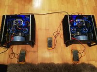
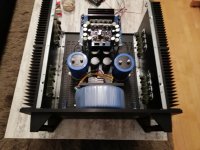
here are some photos of my finished amp...
That's a beautiful amplifier!
here are some photos of my finished amp...
Looks awesome!! Im curious, How much did you end up spending in total all in?
here are some photos of my finished amp...
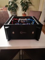
Beautiful artisan work!
Also the inside looks very tidy.
Looks awesome!! Im curious, How much did you end up spending in total all in?
hi.
it was really expensive but i wanted to try the maximum (for me)...
about 1200 - 1400 in all the parts and tools.
Beautiful artisan work!
Also the inside looks very tidy.
thank you.
it took me verly long to sort out how to realize and then to do it...
bias adjustment
hi.
can anybody tell me the minimum bias to drive the amp in class A without any sonic decrease?
thx.
regards
slavko
hi.
can anybody tell me the minimum bias to drive the amp in class A without any sonic decrease?
thx.
regards
slavko
bias
12vdc computer 12cm fan over the heat-sinks.
Last time I checked, 290mvolts? It was easier on my 100 watt speakers, did sound really nice at 3.25mvdc with volume knob at 1\4 turn. Any higher, it wanted to blow-out my windows and added a couple ofhi.
can anybody tell me the minimum bias to drive the amp in class A without any sonic decrease?
thx.
regards
slavko
12vdc computer 12cm fan over the heat-sinks.
Last edited:
correction
I believe I meant 325mvdc.Last time I checked, 290mvolts? It was easier on my 100 watt speakers, did sound really nice at 3.25mvdc with volume knob at 1\4 turn. Any higher, it wanted to blow-out my windows and added a couple of
12vdc computer 12cm fan over the heat-sinks.
Adjust for temp only if you have whimpy heat sinks. Normally adjust up slowly over say an hour or two up to max 325mv across the emitter resisters.
Mark
Mark
thank you for your replies...
i will do that after finishing my project to seperate the KSA-100 into two enclosures...
it´s more work than i thought. but than i will have a good temperature dissipation.
regards
s.
i will do that after finishing my project to seperate the KSA-100 into two enclosures...
it´s more work than i thought. but than i will have a good temperature dissipation.
regards
s.
Hi All,
I own Krell KSA 100, it plays for a while and then goes in protection mode. Its not working now. I tried to on it after few hours but no sound. I just get thud sound when i turn off the switch.
Can anyone help me with trouble shooting or schematic.
Regards,
Nishant
I own Krell KSA 100, it plays for a while and then goes in protection mode. Its not working now. I tried to on it after few hours but no sound. I just get thud sound when i turn off the switch.
Can anyone help me with trouble shooting or schematic.
Regards,
Nishant
After several nights of reading the thread, I'm up to page 136 and I still don't have a very good idea of what it would take to build this amp. What happened to the wiki? Everyone seems to be pointing to it, but the web page is 404 now. Is there a list of suppliers for the transformers, heatsinks and a suitable chassis?


Hi Fenki,
congratulations on your wonderful looking amp.
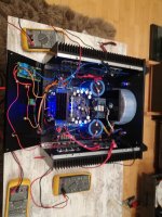
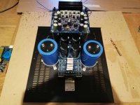
It seems that you used 8 output pairs for each channel.
To do this, did you make any other changes to the circuit i.e. the driver stage?
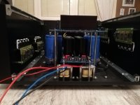
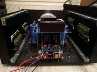
What are the two inductors under the power supply board?
congratulations on your wonderful looking amp.
It seems that you used 8 output pairs for each channel.
To do this, did you make any other changes to the circuit i.e. the driver stage?
What are the two inductors under the power supply board?
It seems that you used 8 output pairs for each channel.
I only see 4 pairs/channel.
- Home
- Amplifiers
- Solid State
- Krell KSA 100mkII Clone