Hi,
jacco said
Which components control the bass quality in the final build of a KSA50 Klone? That knowledge can and should be used to ensure the 100Klone build gives the result that most would expect.
We could start by comparing the differences between the common parts of the two 100s and how they are different from the 50.
The LTP seems similar,
The VAS seems similar,
The FET stage (mk2) is different,
The driver stage is doubled,
the driver bias is reduced,
the output stage is doubled and the bias is +40% (reduced per transistor),
the transformer is bigger,
the capacitance is bigger?,
the layout is different,
What else can be added to the list?
What components in the difference list can be eliminated from the bass investigation? Any?
What components are left that may have an effect on the bass quality?
jacco said
That was the point of my earlier question.A bunch of folks here built a bunch of different KSA50s (Klones), judging one variant doesn't speak for another.
Which components control the bass quality in the final build of a KSA50 Klone? That knowledge can and should be used to ensure the 100Klone build gives the result that most would expect.
We could start by comparing the differences between the common parts of the two 100s and how they are different from the 50.
The LTP seems similar,
The VAS seems similar,
The FET stage (mk2) is different,
The driver stage is doubled,
the driver bias is reduced,
the output stage is doubled and the bias is +40% (reduced per transistor),
the transformer is bigger,
the capacitance is bigger?,
the layout is different,
What else can be added to the list?
What components in the difference list can be eliminated from the bass investigation? Any?
What components are left that may have an effect on the bass quality?
I can't contribute any technical expertise, but I thought I'd search out some part numbers, prices and availability. I filled out most of the BoM with parts available from Mouser. Looks like the MJE15030 is a problem right now (not availalbe at either Mouser or Digikey). C5/C6 has to be sourced elsewhere also, unless a group buy to support 25 boards were accomplished. Not sure if I picked the right footprint for VR1/VR2, couldn't find the 0.1" inline/offset language in the Bourns spec sheet. Don't know if this is of any value to anyone, or even if footprints are correct for other than the obvious, but I wanted to get an idea what the component costs might be. Resistors are Vishay/Dale. The sum includes the "A" version of Q5 & Q6.
Attachments
AndrewT said:will the dv45 play any type of dvd disc no matter which type of recorder it is recorded on?
Nope.
-R/RW and +R/RW are different formats.
Its like CD and MP3, or DVD versus AVI and other compressed formats.
If you write in a different language you also need to be able to read the lingo.
Andrew,
So far I've had no problems playing any type of disks on the DV-45...... It seems to digest just about anything anyone brings over to play at the shootouts. Not true of the JVC that I have though.
There are some semi's that are still in the process of switching to RoHS compliance so that may be the hold up on those. I ave plenty of all the semi's except the current source diodes so I'm set for the most part. Mouser does have those diodes in stock.
Mark
So far I've had no problems playing any type of disks on the DV-45...... It seems to digest just about anything anyone brings over to play at the shootouts. Not true of the JVC that I have though.
Looks like the MJE15030 is a problem right now (not availalbe at either Mouser or Digikey).
There are some semi's that are still in the process of switching to RoHS compliance so that may be the hold up on those. I ave plenty of all the semi's except the current source diodes so I'm set for the most part. Mouser does have those diodes in stock.
Mark
Hi Mark and Jacco,
thanks for the replies.
I have had another look at the spec and note that the CD-R, DVD-R and DVD-RW all use the same hyphen in the notation.
I know that the CD is not -R (that does not exist) so it may be that the hyphen does/does not indicate a DVD compatibility problem.
Can anyone else confirm Pioneer's use of the hyphen and what it means for compatibility of recordable DVD discs?
On second thoughts, a new thread would be better. Do not reply here.
AndrewT said:What else can be added to the list?
olg => feedback factor
current ability
The Krell KMA100 with the regulated driver power supply was FAR BETTER SOUNDING than the KSA100 MK II or the KSA50 in my systems. Dan at Krell even stated this preference, and used the KMA100 to drive his Apogees. Some builders may want to investigate what it would take to construct a KMA100 clone.
cantskienuf said:Looks like the MJE15030 is a problem right now (not availalbe at either Mouser or Digikey).
Arrow has a few hundred MJE15034 and 035s in stock. Specs are very similar to MJE15030/31 exccept higher voltage rating and higher hfe (>100@.5A)
MJE15034G [PB Free] Bipolar Power T0220 NPN 4A 350V
MJE15030G [PB Free] Bipolar Power TO220 NPN 8A 150V
MJE15030G [PB Free] Bipolar Power TO220 NPN 8A 150V
Oops. That's what I get for posting without reviewing the data sheets. I'd used them for a 500 mA regulator, so current rating was not an issue. I think that 4A would be sufficient for dual drivers here.
Prof. Leach recommends these:
2N6474 120 V 4 A 40 W 15hfe 4 MHz
2N6476 120 V 4 A 40 W 15hfe 4 MHz
as a replacement for his amp design.
Can the Krell be that much more demanding?
Seems the MJE15034/5 would be sufficient.
2N6474 120 V 4 A 40 W 15hfe 4 MHz
2N6476 120 V 4 A 40 W 15hfe 4 MHz
as a replacement for his amp design.
Can the Krell be that much more demanding?
Seems the MJE15034/5 would be sufficient.
MJE15030 was just a suggestion for the bias transistor. Use anything you like mentioned in the KSA50 thread.
The trimpots are standard multiturn types that should fit.
The trimpots are standard multiturn types that should fit.
Some builders may want to investigate what it would take to construct a KMA100 clone.
Very easy! Take TAKE THIS REGULATED SUPPLY
section from the KSA-80 and adjust the raw supply and zeners to run the KSA-100 main board and driver stage. Can anyone calculate how much current the main board and drver stage apart would draw. Then we could figure out changing the zeners and resistors.
PWatts..... You might want to make one last change. Split the rails apart between the driver stage and the pre-drivers and add a couple of pads at those points so a seperate reglated power supply like that could be directy wired in. Those building a KSA-100 would merely jumper these two pads. I think this would be a worthy and easy change to do. I for one will be building mine as KMA-100's and slicing the foil with a dremel tool to split the rails looks nasty when you're done. The KSA is way to large and heavy!
Mark
I fully agree Mark. I actually did that in an earlier version but left it out eventually. The idea was for resistors to the LTP to form an RC filter, but jumpers for separate supplies are actually not a bad idea. I'll fit it in this weekend.
I just think the KMA regulators are a bit rough designs.. anybody know of a more modern and elegant idea? I don't have time to design a proper replacement myself.
I just think the KMA regulators are a bit rough designs.. anybody know of a more modern and elegant idea? I don't have time to design a proper replacement myself.
Well it is old but at least its a simple design that is proven in this amp and others. Perhaps after this thread is along a bit more we cold do a new regulator for the KMA-100 as a retrofit😎 .
Mark
Mark
NEW SCHOOL. Worth a look.
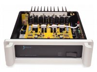
Spectral DMA 360, 1 Mhz single PCB layout. Front end circuits are inside silver cans, front end regulators on main PCB with local small blue caps, output drivers on main PCB with Black Gate cap per VFET, ICs in front are power sequencing and error sensing, small PCB on right side holds protection relays.
DMA-360 Monaural Power Amplifier
Power Output
(continuous): @ 8 ohms - 300 Watts RMS
@ 4 ohms - 533 Watts RMS
@ 2 ohms - 680 Watts RMS
Output Compliment: 90 Amps peak
Frequency Response: +-0.1 dB, DC - 150 KHz
+-1 dB, DC - 1 MHz
+-3 dB, DC - 1.8 MHz
Distortion
Static: less than 0.015% from DC
to 100 KHz, typically
0.009% @ 300 WRMS/8 ohms
Dynamic: 8 Tone Cluster Test 20
KHz @ 500 Hz separation
0.01% @ 8 ohms
0.015% @ 4 ohms
Speed:
Risetime: less than 300 nanoseconds
Settling: 1.5 microseconds to -40 dB
Slew Rate: 600 volts/microsecond
Noise:
Signal to Noise: 97 dB nweighted,
107 dB ASA A
Crosstalk: 98 dB @ full power 8 ohms
Input:
Impedance: 10k ohms
Sensitivity: 1.5 volts / nominal output
Power Supply:
Line Voltage: 100 volts, 120 volts,
240 volts (internal wiring)
AC Voltage Range: +-10%
Maximum Consumption: 2000 Watts
Quiescent Consumption: 250 Watts
Operating Temperature: 0 deg. to +50 deg. Cesius range,
32 deg. to +122 deg. Fahrenheit
Protection Features:
DC Protection Servo: .5 volt range
Current Limit Onset: 90 Amps
Thermal Threshold: Protects at 85 deg. Censius,
185 deg. Fahrenheit
AC Main Fuses: 120v 5A or 220v 2.5A slo blo
Size and Weight:
Dimensions: 20" (50.8 cm) W,
7.23" (18.4 cm) H,
19.6" (49.9 cm) D,
Weight: 67 lbs, 30.4 KG Net
Attachments
Keith O Johnson is an audio genius....! He has been designing audio gear since his high school days and is also one of the inventors of the HDCD format. He designed and built his very famous reel to reel tape machine when he was in high school. I believe it had 3.5 mhz bias! It was very revolutionary in its day and by todays standards the recordings he made with it are amazing.
So he's not entirely new school..... Spectral sold 1mhz bandwidth high end power amps in 1982.
Article -1
Article 2
My favorite Prof. Johnson recording is still the Red Norvo Album he did with the home made recorder.
Mark
So he's not entirely new school..... Spectral sold 1mhz bandwidth high end power amps in 1982.
Article -1
Article 2
My favorite Prof. Johnson recording is still the Red Norvo Album he did with the home made recorder.
Mark
The separate KMA improvised regulator is an excellent idea; it could maybe even be a new thread for serious discussion for the ultimate (and I suppose a few people will go super-insane) regulator to give both the original KSA and KMA a proper whipping.
The problem with regulators are often noise, low-frequency performance and bandwidth. The plain rails are quite noise-free, but suffer from ripple and drift. Elementary regulators may reduce the drift, but add noise. The noise can be addressed with capacitors in its simplest form, and will introduce turn-on thump if not powered up before the output stage. Unfortunately at the low frequencies (not on the power, but on the signal), the regulators that worked so much better at the highs suddenly perform worse than the pure zener-filterered version. Many solutions will also come at the expense of bandwidth, which has to be addressed as well.
Of course one of the most effective solutions would be an integrated low-power switching supply (those small 1A modules), but somehow I figure these will not go down well with the purist and nostalgic people 😉
PWatts,
Regarding verification of your PCB design 😀 :
Though its very hard to follow the routs and foils from side to side I would like to suggest you post following images treated like this:
1) one image: top layer in Red including the components shape (in green)
2) one image: bottom layer in Blue
3) one image: both top and bottom layer together (as a finished board) Red and Blue, including component shape in green.
4) silkscreen (component location) as before.
5) all thru holes/vias (pads on both sides) in black, All pads/footprint on a single layer in black
Of course you could only do this if you have the color option on your PCB CAD software
All four images, post them as pdf-documents.
This should allow for a much easier verification of the board and a decreased risk of faults.
Regards 😎
- Home
- Amplifiers
- Solid State
- Krell KSA 100mkII Clone