We just moved and I now have a larger listening room. So the KSA-50 wasn't quite big enough but it will,work in an upstairs system. Got my Aleph 2's out of storage and am running those. 100 watts class A is about right for this room so that's what made me want to take the KSA-100 prototype that's still sitting in the garage and finish it properly. The transformer in it now gives me 70 volt rails! So when I was doing the initial tests I used a 20 amp Variac to bring it down. I don't want to unwind this particular transformer because it's a 2KVA dual secondary transformer from a huge Crest amplifier.. It might come in handy to build that KSA-200 some day.
Mark
Mark
Hello,
I had the KSA 100 MK 2 and the KSA 100 MK1.
My MK 1 was one of the last Version.
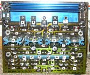
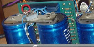
Look at the Picture my MK 1 Board.
What ist the difference to the MK 2 Board
KSA 100 MK 1 is more musically as the MK 2.
More tube Sound, but a Little less bass control.
Bye Alex
I had the KSA 100 MK 2 and the KSA 100 MK1.
My MK 1 was one of the last Version.
Look at the Picture my MK 1 Board.
What ist the difference to the MK 2 Board
KSA 100 MK 1 is more musically as the MK 2.
More tube Sound, but a Little less bass control.
Bye Alex
Hello,
I had the KSA 100 MK 2 and the KSA 100 MK1.
My MK 1 was one of the last Version.
Look at the Picture my MK 1 Board.
What ist the difference to the MK 2 Board
KSA 100 MK 1 is more musically as the MK 2.
More tube Sound, but a Little less bass control.
Bye Alex
Attachments
I don't think I've ever seen a KSA200 in the flesh, but by running the numbers I assume it must be a monstrous beast.
Yup...I actually owned a KSA-250 and it was NOT like the KSA-200. The KSA-250 was a Sliding Bias Design (even tho it wasn't marketed as one), and did not put out the heat like the other non Sliding Bias amps. The KSA-200 is the one that put out the most heat of the KSA lineup... My KSA-50 Clone puts out a fair amount of heat and pulls around 6-7 amps from the wall...just a little less than the KSA-250 I had...My KSA-50 has a 1.2KVA tranny, while the KSA-250 had a 4KVA tranny.. I actually like the KSA-50 Clone a little more than the KSA-250 (Builders Bias?)...both are very good amps!! Ended up selling the 250 as I had someone that HAD to have it....took the proceeds and building another KSA-50 from Pink's Boards...this one will go in a donor KSA-300 Chassis I bought years ago with same 1.2kv toroidal tranny....
Digression Warning On: Now I know I not on the Electronics level as many of you here...but if 120VAC Mains x 20 amp service gets you 2400VA....how would you ever get into than residual power from a 4KVA tranny?? Is there even a 30 or 35 amp Service available? I have 15 amp service in my office / listening room and seems plenty for all I need to do. Digression Warning Off.
Last edited:
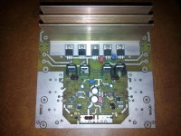
I found the MK-2 version to be the better one. It is a bit more complex than the Mk 1 version though. Here is a picture of the board from the KSA-100 thread It is the MK-2 version.
Hello Mark Allen,
Yes, a bit. Maybe better an lower impedance.
The KSA 100 MK2 have a other power supply with two rectifier and Sprague capacitors.
The KSA 100 MK1 is much more livelier and full tube Sound.
I can't see a difference to my MK1 Board and Mk2 Board.
thanks Alex
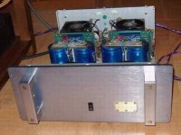
My MK 1 and MK 2
Attachments
Last edited:
Use the 220/240Vac service that comes into your house/office......................
Digression Warning On: Now I know I not on the Electronics level as many of you here...but if 120VAC Mains x 20 amp service gets you 2400VA....how would you ever get into than residual power from a 4KVA tranny?? Is there even a 30 or 35 amp Service available? I have 15 amp service in my office / listening room and seems plenty for all I need to do. Digression Warning Off.
That's the two phases that seem to be available on most North American distribution boards.
In large cinema sound systems I have run amp racks on 220 volts in several cases. It here are some racks with ten or more 400 WPC power amps it makes sense. When we run them on 120 volts we need at least three or four 120 volt circuits per rack. Running 220 you need only two circuits. Saves money on electrical work and ordering the amps with 240 volt primaries there is no extra charge.
Mark
Mark
OK, makes sense...The fix is to wire the amp to 240VAC, and run a new 2 phase circuit like my electric dryer...
But I never had an issue with the 15amp service...
But I never had an issue with the 15amp service...
Attachments

Last edited:
The first thing I'd be doing to that MK1 is replacing the 30 year old main electrolytic's. I see a 1984 code date on one of them!! I will try to post schematics of both types today so you can see difference.
Mark
Mark
In the process of procuring parts for a 100mkII build. The pre-driver mosfets I'm planning on using are 2SJ313/2SK2013. How do we determine the proper region for these particular fets to be operating in? I've read the entire thread and I remember AndrewT saying that he'd put a resistor in series with a higher current rated diode to bring it down to roughly 3mA. Being that the 1N5309 is next to impossible to find (Newark says some are on order).....would something like these work?
E-272 Semitec | Mouser
E-352 Semitec | Mouser
thanks
-John
E-272 Semitec | Mouser
E-352 Semitec | Mouser
thanks
-John
I'm curious if replacing 1N5309 with JFET current source is a simpler and better option then finding the original
1N5309
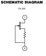
Indeed, the schematic/boards I'm using also spec CR300, which is a jfet current source in one package, as a direct replacement for 1N5309. But along with the 1N5309 is tough to impossible to get a hold of. The board I have also specs a LM334 in the D5/D6 position.
If going for the jfet/resistor as our D5/D6, which jfet/resistor combination would be suitable for 3mA, using 2SJ313/2SK2013 fets? I'm assuming a low noise jfet would be of some importance.
I'm curious if replacing 1N5309 with JFET current source is a simpler and better option then finding the original
Indeed, the schematic/boards I'm using also spec CR300, which is a jfet current source in one package, as a direct replacement for 1N5309. But along with the 1N5309 is tough to impossible to get a hold of. The board I have also specs a LM334 in the D5/D6 position.
If going for the jfet/resistor as our D5/D6, which jfet/resistor combination would be suitable for 3mA, using 2SJ313/2SK2013 fets? I'm assuming a low noise jfet would be of some importance.
Attachments
FYI: According to the newark website the 1n5309 is in stock, with more than 100 remaining...not that I bought any to test the hypothesis...
Stuart
Stuart
Awesome, yesterday there were 2 avail.
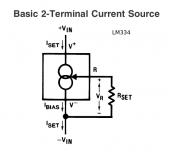
For the sake of trying to understand....I've been reading AN103 document (attached, and a bit beyond my knowledge), I realize it may be basic questions, but in regards to the jfet current source....Being that I'm using different mosfets than the original, 3mA was set for the orig VN0210N5/VP0210N5. I could compare datasheets, but not really sure what parameters need to match or be close. And....I'd like not to spend 60USD on....diodes
For the sake of trying to understand....I've been reading AN103 document (attached, and a bit beyond my knowledge), I realize it may be basic questions, but in regards to the jfet current source....Being that I'm using different mosfets than the original, 3mA was set for the orig VN0210N5/VP0210N5. I could compare datasheets, but not really sure what parameters need to match or be close. And....I'd like not to spend 60USD on....diodes
Attachments
Last edited:
Diy X-Aleph and Krell KSA 100
Hello,
Who can tell me which diy amp is better ?
The original Krell have good tube Sound but the slew rate is not so good as Alephs.
How are the Diy amps ?
Is the X-Aleph better as Krell Ksa 100 or KSA 50 ?
Best regards Alex
Hello,
Who can tell me which diy amp is better ?
The original Krell have good tube Sound but the slew rate is not so good as Alephs.
How are the Diy amps ?
Is the X-Aleph better as Krell Ksa 100 or KSA 50 ?
Best regards Alex
- Home
- Amplifiers
- Solid State
- Krell KSA 100mkII Clone