I don't have access to the preamplifier now, what model are the diodes in the kit? Heneser advised me to try SB 550 diodes. Which I should order though
Guys a little help... the phono buzzes a lot as I turn up the volume knob, I rewired everything with shielded cables, I made the change by replacing the 2055 with a mj3000 and placed a 14v zener diode (as read in another post) but nothing to do the buzz is always present.... What else do you recommend? Thank you
Possible ground loop issue? Perhaps share some photos of your build for some visuals as assistance.
Hello. I just ordered a complete kit including the transformer and the case. Now waiting for the kit to arrive. In the meantime I have read through all this thread. A lot of information. A bit scattered. I am thinking to make a list of recommended modifications and place it here for a more easier way to track down all the recommended modifications. I hope this kit wont have too much hum.
I got a bit of a vacuum tube bug, perhaps a bit of a rabbit hole. I build a couple of EAR834 with the modifications recommended on Lencoheaven. I build also a Klimo LAR.
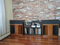
Both of them have a bit of hum, more than i would like. It is possible the hum is more annoying because I have Klipsch Belle for speakers and at a rated sensitivity of 103dB. I build the Belle myself and use the driver kit and crossovers from Volti. The speakers are great.
On M77 I was wondering about what RIAA modification would be needed to 12AT6 tubes instead of the 12AY6. The gain is almost the same but there are other tube differences which would affect RIAA. 12AT6 are cheaper even in NOS version.
I am attaching the picture of my speakers I build.
I got a bit of a vacuum tube bug, perhaps a bit of a rabbit hole. I build a couple of EAR834 with the modifications recommended on Lencoheaven. I build also a Klimo LAR.
Both of them have a bit of hum, more than i would like. It is possible the hum is more annoying because I have Klipsch Belle for speakers and at a rated sensitivity of 103dB. I build the Belle myself and use the driver kit and crossovers from Volti. The speakers are great.
On M77 I was wondering about what RIAA modification would be needed to 12AT6 tubes instead of the 12AY6. The gain is almost the same but there are other tube differences which would affect RIAA. 12AT6 are cheaper even in NOS version.
I am attaching the picture of my speakers I build.
Attachments

I meant to say if I could use 12AT7 instead of the 12AY7. I am still learning and, LTSpice is above my head at this time, I hope one day I will be able to understand how LTSpice works and then play with different settings for the RIAA.
These are the modifications recommended throughout this thread.
1. Power supply section.
4. Line output coupling capacitors, use good quality 2 capacitors preferably 1uF/250V
5. Change resistors to 56K 3-5W (Mills WW resistors) x6 and 2K2 1W x4
6. Disable the relays which shuts down filament and high voltage supply to phono section.
7. To reduce hum, connect PCB ground to the chassis and also use shielded cables
8. if there is noise when switching inputs. https://www.diyaudio.com/community/...hone-preamp-clone-project.358732/post-7337095
9. Stand by switch wiring. https://www.diyaudio.com/community/...hone-preamp-clone-project.358732/post-7252278
10. to be determined. 12AT7 RIAA components values. 6N1P RIAA components values. Those are much cheaper vacuum tubes to be found in NOS version.
Did I make any mistakes? Any additions to this list?
1. Power supply section.
-Replace the 2N3055 with a good, sturdy darlington (MJ3000 or MJ3001 will do fine), make sure to apply thermal grease as it will get a little hotter than before.. Add a 14V zener diode on the bottom side, as indicated. Example of 14V Zenner BZX55C14
-Replace trimmer pot with a fixed 100R or another post recommended 500R
-Use choke 20H 50mA
-replace kit socket with 7-pin ceramic socket for 6X4 tube
-put 0.1uF capacitors in parallel to the electrolytic capacitors
2. RIAA Section-Change 33K Resistor to 50K
-Add 10K Resistor in serial with 1nF capacitor
-For RIAA section use good quality, very low tolerance and matching resistors 300K, 10K, 30K, 50K,
-For RIAA section use good quality capacitors 1nF/50v and 10nF/50v
3. Coupling capacitors, use good quality 4 capacitors 0.22uF/250V4. Line output coupling capacitors, use good quality 2 capacitors preferably 1uF/250V
5. Change resistors to 56K 3-5W (Mills WW resistors) x6 and 2K2 1W x4
6. Disable the relays which shuts down filament and high voltage supply to phono section.
7. To reduce hum, connect PCB ground to the chassis and also use shielded cables
8. if there is noise when switching inputs. https://www.diyaudio.com/community/...hone-preamp-clone-project.358732/post-7337095
9. Stand by switch wiring. https://www.diyaudio.com/community/...hone-preamp-clone-project.358732/post-7252278
10. to be determined. 12AT7 RIAA components values. 6N1P RIAA components values. Those are much cheaper vacuum tubes to be found in NOS version.
Did I make any mistakes? Any additions to this list?
Could you share what modifications you made in order to make 6N1p work? I used those in an EAR834 build and they sound greatHi folks
I used this same K77 board to build a preamp last year and have never got round to documenting it here. I did not stick to the original recipe and used the board as more of a basic platform to work from. It is certainly a well made board with good quality traces and lots of room for component changes etc. There are certainly some strange choices made in the power supply especially the filament supply as noted by others.
I wanted the cascode phono input in particular. This allows high gain in the first stage without high input capacitance. I am using MM cartridges and having high input capacitance can cause problems with many cartridges. I have not been disappointed with the results. The phono pre sounds fantastic without the rough edge that my solid state OPA2134 based preamp seems to add to the sound. I had to re calculate the RIAA network to get the curve right. I used different tubes. 6N1p with the option of using other 6dj8, 6922 types. I had lots of them around and they are inexpensive. The phono stage is very quiet, having inaudible noise from the listening seat. It may even be quieter than the SS preamp I have. Gain is 36db in my configuration. I made a few changes to circuitry. I used mosfets for the cascode elements saving a tube. I also used single tube sections for the gain stage in the line stage resulting in phono and line stage using 3 tubes each.
To derail with the filament supply I wired the tubes in each amp section, line and phone, in series and power them with 18.9volts. This reduces the current to a manageable 600 ma per section or about 1.2 amp total. Wired in parallel it would be 3.6 amps for 6.
I also included a wireless remote alps volume control and input selector, fine gain adjust controls for each channel and a High frequency level control similar to what Festo audio puts on their preamps so you can reduce the HF energy for bright recordings. I used a separate power supply and a regulated B+ With delayed startup and I am just now adding muting circuitry to prevent turn on /off bumps in the output. I’m very pleased with the results and the boards proved to be well made during all my trace cutting and modifications made to get the result I wanted.
I am more than happy to provide my solution to a phono pre using 6N1P for the K77 board. I looked back at my notes and found a hand drawn diagram of the phono stage as seen below. The power supply is not as drawn. I believe I had RC filtering between the phono input stage and the 2nd gain stage/ output CF. I reduced the number of tubes to 6 total in the preamp by replacing the phono tube cascode with mosfets and also using a single vs doubled up gain stage in the line section. Filaments for the 3 tubes in each section, phono and line, are wired in series and supplied with 18.9v regulated DC from a LM338 TO3 regulator. Total filament current is about 1.2 amps with Line and Phono on. I kept the phono stage on/off feature and have about a 1 minute delay built in when I switch on the phono stage to eliminate any turn on issues. Rewiring the filament from parallel to series was the most difficult change to implement. There were many traces cut and jumpers installed on the board by the time I was done. I did not want to buy parts to create a 6.3v 4 amp power supply, so the series option is what I chose. As noted in a previous post this phono stage is very quiet and distortion figures are low. I measured .2% THD at 6.7volts out at 1khz on a Keithley 2015 distortion meter. That was an input of 100mv for a gain of 67 or 36.5db. This amount of gain works well for my setup of MM cartridge an AT VM540MR
This was a pandemic project and built using the parts I had on hand. Some of the resistor values may be uncommon. I found the K77 board was of very high quality and had lots of space to install parallel resistors or make other changes of the PCB layout necessary to accommodate using the 6N1P. The end result was a very nice preamp for my purposes and it has worked flawlessly for almost 2 years now. One thing is certain. This preamp is no longer a K77 clone but something very different. Different tubes, solid state cascode, changes to the power supply etc. have produced something new from what is a very well executed and versatile DIY PCB.
Cheers
Brian
This is great. Thank you for sharing. Does using Mosfets as tube cascode change the tube sound of the preamp?
I think I will buy a second PCB to be able to play with it and make these modifications. Then I can compare the 2, original M77 versus your modified version. I have a good power source I used for EAR834 which I think would be able to handle the filament voltage for the 6N1p
6N1p is good sounding tube and very cheap. Could I still use 6N1p instead of the Mosfet? I apologize if this is a dumb question. I am an amateur which wants to learn.
Eliad
No apologies necessary here for wanting to learn!! Yes, of course you can use a tube cascode, or transistor, whatever you want. The main benefit as I see it for the cascode is that the input capacitance of the phono input tube is low because there is no voltage swing at the plate of the input tube and hence no Miller effect multiplication of the input capacitance. This is crucial to getting good sound from a lot of MM cartridges which provide the flattest response when loaded by a low capacitance. When comparing circuits like a phono EQ for sound quality remember that even small variations in response can change the character of the sound if they occur over a large bandwidth. You should note any differences in RIAA response between the 2 phono preamps and take that into consideration when comparing for sound quality. The most basic function of the circuit is to accurately follow the RIAA curve. If, for instance, you have 2 preamps and one is 1db high on the HF eq and a second one that is 1db down, you will have a 2db variation over the entire HF bandwidth. This will be audible and is not strictly due to topology or solid state versus tube differences.
What I notice about the K77 phono versus an OP2134 op amp based design is that the HF is more relaxed and never harsh, while the K77 is absolutely unflappable with high energy records, always staying sorted out and never becoming harsh or overloaded. This is in spite of the fact that both preamps have RIAA response within +-.2db over 20 -20khz so something else is going on. All these observations are very unique to each system and listener and can provide no end of entertainment, satisfaction or frustration for the DIY practitioner. Have fun, learn and enjoy!
What I notice about the K77 phono versus an OP2134 op amp based design is that the HF is more relaxed and never harsh, while the K77 is absolutely unflappable with high energy records, always staying sorted out and never becoming harsh or overloaded. This is in spite of the fact that both preamps have RIAA response within +-.2db over 20 -20khz so something else is going on. All these observations are very unique to each system and listener and can provide no end of entertainment, satisfaction or frustration for the DIY practitioner. Have fun, learn and enjoy!
HiYou may want to increase the output cap of the line stage to 1uF (depends on your power amplifier....), and using good caps definitely helps. I used Jansen Silver Caps. Checked out MIFLEX and the website did not tell much about them, what kind of capacitors are they?
when i use phono i have ..pup pup.. noise on one side (Left) who can help me ?
Member
Joined 2009
Paid Member
Interesting observations. I wonder if the tubes have more headroom, better response to clipped signals.Snip…
What I notice about the K77 phono versus an OP2134 op amp based design is that the HF is more relaxed and never harsh, while the K77 is absolutely unflappable with high energy records, always staying sorted out and never becoming harsh or overloaded. This is in spite of the fact that both preamps have RIAA response within +-.2db over 20 -20khz so something else is going on. All these observations are very unique to each system and listener and can provide no end of entertainment, satisfaction or frustration for the DIY practitioner. Have fun, learn and enjoy!
Yes, they definitely have more headroom. At least 100v p/p output before clipping. I never tested it for max output although 1% distortion came at about 17vrms out. Also the cartridge is loaded with the correct capacitance versus the op amp pre which has too much input capacitance. This reduces overshoots and resonant behaviour in the cartridge output. Also more 2nd order distortion with the tubes and a very gradual approach to clipping.Interesting observations. I wonder if the tubes have more headroom, better response to clipped signals.
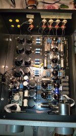
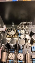
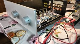
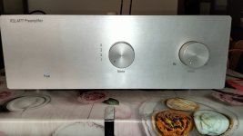
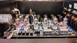
when i use phono i have ..pup pup.. noise on left side 😐Finally got around to take some pictures of my build, please see attachments. I tried to use copper where possible, just like in the original 😀
Also, fully potted mains transformer attached with springs and foam, a line filter, and additional bypassing on the supplies (the small black film caps).
You can also see the MC input transformers on the backside, giving me both asymmetric and symmetric inputs. The symmetric outputs are connected asymmetricaly for the moment, work in progress..... The volume pot is a chinese stepped attenuator, works fine in my opinion.
The coupling caps are Jansen silver caps, and the RIAA caps are Silver Mica. Wiring is done with silver coated solid copper and cloth isolation.
Enjoy 😀
Can you help me please? I waiting for your halp ☺️
Last edited by a moderator:
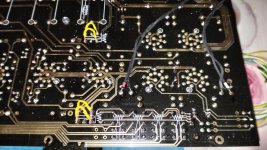
Hi, I performed the Hesener modifications and everything is perfect, no hiss, nothing at all, the only problem is that instead of having 12.6v on the test point I have 11.8v.CIAO
quando uso phono ho ..pup pup.. rumore su un lato (a sinistra) chi può aiutarmi?
I have to try to replace some components I ordered from Banzai music and see if it solves the problem. The only noise I hear is when he switches the selector, otherwise everything is fine.
I attach some photos.
CIAO
when i use phono i have ..pup pup.. noise on one side (Left) who can help me ?
Attachments
-
 IMG20230507235057.jpg407.5 KB · Views: 206
 -
 IMG20230507232220.jpg373.5 KB · Views: 188
 -
 IMG20230507225649.jpg323.3 KB · Views: 175
 -
 IMG20230507211235.jpg362.2 KB · Views: 152
 -
 IMG20230410004434.jpg321.1 KB · Views: 173
 -
 IMG20230410004250.jpg191.8 KB · Views: 159
 -
 IMG20230409183809.jpg336.5 KB · Views: 193
- Home
- Amplifiers
- Tubes / Valves
- Kondo KSL-M77 phono preamp clone project