
looking at the board and the components i got. For the balance potentiometer on the PCB, do I need to add more resistors in the area since I am not going to use a balance potentiometer?
In the package I got a Mute switch, the front panel has a spot for it, therefore I will have to install it. Where or how do I wire this Mute switch?
In the package I got a Mute switch, the front panel has a spot for it, therefore I will have to install it. Where or how do I wire this Mute switch?
I am interested in building the clone of the Kondo KSL-M77. My first question before starting this: if there is anyone who has compared the musical rendering of his clone with the original. This question arises: is the sound rendering the result of an original typology in the unprecedented design circuitry? Or it seems to me that the designer made the Ksl M77 famous and very expensive because he managed to obtain enchanting sounds with a choice of very high quality components, almost all self-built in silver.
Due to my availability and ability I could never do what the manufacturer has developed, so if I used quality components I would never reach the musical rendering of the original with my clone?. Would I have a preamplifier with musical renderings that I can find with clones of other projects?. I would like to receive your opinions
Due to my availability and ability I could never do what the manufacturer has developed, so if I used quality components I would never reach the musical rendering of the original with my clone?. Would I have a preamplifier with musical renderings that I can find with clones of other projects?. I would like to receive your opinions
Today I received the 6x4 tube replacement. Turned on and no sparks, no drama.
I have a 60Hz hum. I did the filament power modifications as advised. I used shielded cables for connection. The PCB is ground is connected to the case. Ground for the power line is connected to the case. I used the star ground scheme with the star point on the PCB.
My speakers have a high sensitivity and the hum is much more noticeable due to high sensitivity at 103dB.
I am not an electronic engineer and I don't understand all of this. Typically the power line hum is coming from the filaments or from the HT power?
I am open to suggestions
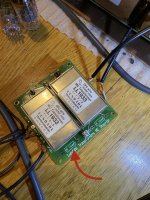
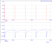
(I use Lundahl ll1933 but this have ( Huuum)and noise!I looked at the previous posts, and if I am not mistaken, the values you reported are:
Incoming AC: 13.3V
DC on the collector of the MJ3000: 13.1V
DC on the tubes (test pins): 11.8V
If that is correct, there is a huge voltage drop in the rectifier for the tube supply, which is odd. These diodes should be getting very very warm..... And it means, the transistor is not regulating anything and the hum removal is not really working.
Not sure if you can, but it would be interesting to change the rectifier diodes to SB550 (this is a 50V, 5A schottky rectifier diode which should fit). And, if possible, to measure the temperature of the rectifier diodes you have in there today, just to prove my point 😀
Nice speakers, by the way!
Isend photo now , i hope you help me 😉
Attachments
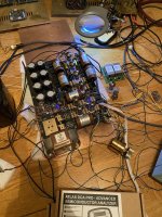
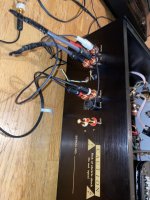
I noted you have a resistor on the RCA inputs. What is the purpose for it, and what value are those resistors?Finally got around to take some pictures of my build, please see attachments. I tried to use copper where possible, just like in the original 😀
Also, fully potted mains transformer attached with springs and foam, a line filter, and additional bypassing on the supplies (the small black film caps).
You can also see the MC input transformers on the backside, giving me both asymmetric and symmetric inputs. The symmetric outputs are connected asymmetricaly for the moment, work in progress..... The volume pot is a chinese stepped attenuator, works fine in my opinion.
The coupling caps are Jansen silver caps, and the RIAA caps are Silver Mica. Wiring is done with silver coated solid copper and cloth isolation.
Enjoy 😀

I stand corrected. The hum I have is at 120Hz and it is about 50dB when my amp volume is at 50%. I understand this could be related to ground loop, I will work through the ground scheme and see if I can improve on it. Any suggestions?
Those resistors should discharge any DC coming from a source, as I have noted a clicking sound when changing the input. 100k in my case, but they can be anything maybe up to 500k.I noted you have a resistor on the RCA inputs. What is the purpose for it, and what value are those resistors?
Finally found out the clicking noise is caused by something else (relay decoupling)...... This can be cured with a diode in parallel to the relay coil, with the cathode to "+"
Hi Eliad, try to connect the GROUND cable to the "-" connection on the input side of the PCB, not the central ground point in the middle of the PCB, maybe that helps. In my case, everything is referenced to the input ground (the nice copper bracket you have around your RCA sockets).
Just found out that my clone is showing a mysterious issue: When something is connected to the LINE input, but the input selector is switched to PHONO, there is a small but noticeable coupling that can be heard at the output (need to turn up the volume though). It is clearly coupling into the phono stage as the sound is muffled because of the RIAA correction. This is despite the input relays short-circuiting all other inputs when not selected.....
Anybody else have that problem????? Guess it could be solved by routing shielded cables directly to the relays, but I wanted to ask if anybody else has that issue.....
Anybody else have that problem????? Guess it could be solved by routing shielded cables directly to the relays, but I wanted to ask if anybody else has that issue.....
here is my build. I like the sound even with the cheaper components. Unfortunately I have quite a lot of 125Hz hum. I am thinking perhaps I should use a different power supply than the build in.

My preamp! Finish and this pre dont have noise !
I use vintage NOS Gresham oli transformer
Thanks Bigun and hesenere ⭐️⭐️⭐️⭐️⭐️
I use vintage NOS Gresham oli transformer
Thanks Bigun and hesenere ⭐️⭐️⭐️⭐️⭐️
Attachments
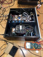


excellent. I noticed you are not using the build in filament power, what do you use for filament power supply. I think my problem is with the filament power, I did do the modifications as described by hesener but I think I need something betterMy preamp! Finish and this pre dont have noise !
I use vintage NOS Gresham oli transformer
Thanks Bigun and hesenere ⭐️⭐️⭐️⭐️⭐️
use LT1963A reglator !excellent. I noticed you are not using the build in filament power, what do you use for filament power supply. I think my problem is with the filament power, I did do the modifications as described by hesener but I think I need something better
https://jimsaudio.com/lt1963a-very-low-noise-1-2v-20v-1-5a-6a-power-supply-pcb-w-soft-starting/
It is very good!
I have part for this boart and i can send you all oart for free if you pay shopping cost! ! If you are in EU i can send …
I have allso LT reglator ! You know if you want order part must you pay many money!
thanks for everything
Thanks for everything !excellent, enjoy!
- Home
- Amplifiers
- Tubes / Valves
- Kondo KSL-M77 phono preamp clone project