Your picture Shows 78% distortion, looks like you have severe clipping going on. The m77 should have about 0.1% at 0dBm = 0.775V at the output. Please check the RMS output voltage and adjust the volume pot accordingly, thanks

Time for an update...
I procured a Matched Quad of GE JG-6072s which I put in the preamp section. The result? Made all the difference in the world. I would now say that my KSL sounds EPIC. But I paid $200 for the quad... which was a good deal...
And putting the 6072s in stopped the little bit of hum that I was getting.
I procured a Matched Quad of GE JG-6072s which I put in the preamp section. The result? Made all the difference in the world. I would now say that my KSL sounds EPIC. But I paid $200 for the quad... which was a good deal...
And putting the 6072s in stopped the little bit of hum that I was getting.
Hi Rodango, unfortunately I'm at a standstill, the dealer from whom I ordered the 12ay7 cheated me and is an Italian.Time for an update...
I procured a Matched Quad of GE JG-6072s which I put in the preamp section. The result? Made all the difference in the world. I would now say that my KSL sounds EPIC. But I paid $200 for the quad... which was a good deal...
And putting the 6072s in stopped the little bit of hum that I was getting.
I'm happy with your result 👍💪
Hello and Happy New Year
Hi everyone, I've been reading the post up and down since Nov, while awaiting for my kit. Just got my kit today and already have all the upgrade parts suggested in my cart from parts connexion. Thanks for all the details and sharing, this has helped me tremendously! I'm going with the upgraded resistor for 33k and 30k to 50k, I also read the 300k should be upgraded as well? If so to what value? Thanks in advance and everyone's contribution.
Hi DerekRonin, sounds like you are in for a nice adventure! Modifying the 33k to 50k is the most important change. You can leave the 33k and 300k as is.
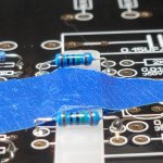
Just choose "good" resistors (suit your taste 😀 ) and capacitors, and make sure to measure the parts, so that they are as equal as possible between the two channels - especially the capacitors.
Just choose "good" resistors (suit your taste 😀 ) and capacitors, and make sure to measure the parts, so that they are as equal as possible between the two channels - especially the capacitors.
Thanks again Hesener, I've been following each of your post closely and trying my best to match all your modifications. Will probably go with your linestage resistor mods as well. Went with Jantzen red caps(.22 and 1.0), Silver were a lil too pricey here in the states at the moment. Going to take it slow and share my progress once done.Hi DerekRonin, sounds like you are in for a nice adventure! Modifying the 33k to 50k is the most important change. You can leave the 33k and 300k as is.
Just choose "good" resistors (suit your taste 😀 ) and capacitors, and make sure to measure the parts, so that they are as equal as possible between the two channels - especially the capacitors.
Hi did you had to short/bridge the 3 connections on each side? Or just the top and bottom leads?
I ended up removing the two relays completely and shorted the top and bottom connections. I don't think it matters if you short all three.Hi did you had to short/bridge the 3 connections on each side? Or just the top and bottom leads?
Thanks! I think I'll do the same,I ended up removing the two relays completely and shorted the top and bottom connections. I don't think it matters if you short all three.
I may need to do this as well, after the other mods. If you don't mind, may need to bother you for some info later once I get the other mods completed.The rotary switch is in fact a 100k pot (+ 10k resistor), to adjust the input load for the MM input. And, as it is in parallel to the MC step-up transformer, it also works when the MC input is selected, here it will adjust from 100ohm to 1.1K.
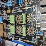
On the bypass caps, I used 100nF, mostly because I had some with long leads that would nicely fit on top of the resistors without too much hassle. Next on the list was to make a 4-channel superreg (like the one from Allen Wright of Vacuumstate fame), one day I will get around to that project 😀
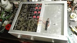
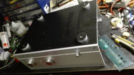
Far from ready from housing it in a chassis at this moment, but just out of curiosity, what are some of the general dimensions of everyone's build? I'm still debating on whether to house the tubes or have them exposed. (I'm leaning towards having them exposed, easier for swapping) Just looking around some the pre-fab chassis are upwards of $200 for a size to fit this board. Did anyone fabricate their own?
I have made my own chassis  Dimensions are in .dxf file attached. Not with every detail drawn, just coarse drawing
Dimensions are in .dxf file attached. Not with every detail drawn, just coarse drawingAttachments
-
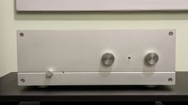 photo_2023-01-14_21-26-54.jpg79.4 KB · Views: 195
 -
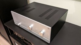 photo_2023-01-14_21-27-06.jpg77.4 KB · Views: 190
 -
 photo_2023-01-14_21-27-03.jpg80.6 KB · Views: 213
 -
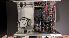 photo_2023-01-14_21-26-59.jpg142 KB · Views: 232
 -
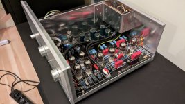 photo_2023-01-14_21-27-09.jpg147.4 KB · Views: 242
 -
 IMG_20220926_190734.jpg343.6 KB · Views: 235
 -
 IMG_20220926_200123.jpg247.5 KB · Views: 221
 -
kondo.dxf.zip28.8 KB · Views: 107
That's amazing! Thanks for sharing! I was thinking about going through the route of thrift store shopping for an old receiver and seeing if I could repurpose it.I have made my own chassis
Noticed most shorted their balanced pot, I have an MN-taper pot with a center click, was there anything special you did to make it work? If convenient, any close-up pics of how you wired this?Just to follow myself up. I just realised that there is something called a balance potentiometer (MN-taper), and that I had bought one some time ago without realising what it was. With some experimentation and measurement with my multimeter I managed to wire it to the M77 pcb. It seems to function properly. I think. It attenuates 3.5 dB maximum, which should be enough to to adjust for a slight asymmetric listening position or some imbalance in the sound.
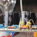
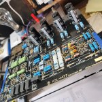
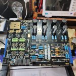
Most parts has been populated, awaiting for the upgrade caps and resistors to come in. Figured with all the questions, I can share some progress update. Linestage resistors (partial) are in (tks hesener) for this. Updated with some Panasonic power caps & some ERO film/foil caps .01uf. Still shopping for a transformer, choke, chassis solution and tubes. Already looking to build a power amp to pair this with (I got bit by the tube bug recently), any recommendations?
Attachments

Man, this thread kind of ran away didn't it?
I never did finish up my K77 PCB and all. I think I may strip the capacitors off of it and pass it along to someone else. Anyone in the SF Bay area here in California looking for a project? Come grab it and the PCB is yours 🙂
I never did finish up my K77 PCB and all. I think I may strip the capacitors off of it and pass it along to someone else. Anyone in the SF Bay area here in California looking for a project? Come grab it and the PCB is yours 🙂
Oh no way? How come? lost interest? I'm here in S. Cal, had a few buddies asking about my build over the holidays, as they saw it on the bench. Perhaps they may have some interest.Man, this thread kind of ran away didn't it?
I never did finish up my K77 PCB and all. I think I may strip the capacitors off of it and pass it along to someone else. Anyone in the SF Bay area here in California looking for a project? Come grab it and the PCB is yours 🙂
- Home
- Amplifiers
- Tubes / Valves
- Kondo KSL-M77 phono preamp clone project