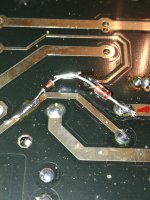
Someone in the thread has probably already identified the input stage topology, but I admit to not having read completely through the thread. If not, however, it looks to me like a cascode, except, rather than the expected fixed-bias on the cascode triode, it is grid-leak biased. I don’t recall having before seen this particular cascode biasing configuration. I’m uncertain of what the objective advantages would be. My guess is that it was chosen because Kondo-san thought it sounded better than alternative biasing methods.anybody know the reason for this 10Meg resistor?
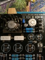
Hi, also in the process of building this clone, and I came across this 10M resistor for the upper triode in the input stage. Simulation shows strong increase in the higher frequencies, that disappears when the resistor is reduced to ~200k.
Scratched my head but couldnt come up with an explanation..... Is this on purpose? Kondo magic?
😀
Last edited:
Hi folks
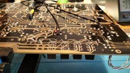
I used this same K77 board to build a preamp last year and have never got round to documenting it here. I did not stick to the original recipe and used the board as more of a basic platform to work from. It is certainly a well made board with good quality traces and lots of room for component changes etc. There are certainly some strange choices made in the power supply especially the filament supply as noted by others.
I wanted the cascode phono input in particular. This allows high gain in the first stage without high input capacitance. I am using MM cartridges and having high input capacitance can cause problems with many cartridges. I have not been disappointed with the results. The phono pre sounds fantastic without the rough edge that my solid state OPA2134 based preamp seems to add to the sound. I had to re calculate the RIAA network to get the curve right. I used different tubes. 6N1p with the option of using other 6dj8, 6922 types. I had lots of them around and they are inexpensive. The phono stage is very quiet, having inaudible noise from the listening seat. It may even be quieter than the SS preamp I have. Gain is 36db in my configuration. I made a few changes to circuitry. I used mosfets for the cascode elements saving a tube. I also used single tube sections for the gain stage in the line stage resulting in phono and line stage using 3 tubes each.
To derail with the filament supply I wired the tubes in each amp section, line and phone, in series and power them with 18.9volts. This reduces the current to a manageable 600 ma per section or about 1.2 amp total. Wired in parallel it would be 3.6 amps for 6.
I also included a wireless remote alps volume control and input selector, fine gain adjust controls for each channel and a High frequency level control similar to what Festo audio puts on their preamps so you can reduce the HF energy for bright recordings. I used a separate power supply and a regulated B+ With delayed startup and I am just now adding muting circuitry to prevent turn on /off bumps in the output. I’m very pleased with the results and the boards proved to be well made during all my trace cutting and modifications made to get the result I wanted.

Yes, it seems the approach is grid-leak biasing, that is what most experts around here concluded. I simmed this and also "regular" biasing, and I also measured both versions. While in the simulation the grid leak bias caused a loss of high frequencies, the measurements for both showed no difference whatsoever.Someone in the thread has probably already identified the input stage topology, but I admit to not having read completely through the thread. If not, however, it looks to me like a cascode, except, rather than the expected fixed-bias on the cascode triode, it is grid-leak biased. I don’t recall having before seen this particular cascode biasing configuration. I’m uncertain of what the objective advantages would be. My guess is that it was chosen because Kondo-san thought it sounded better than alternative biasing methods.
Finally I kept the regular bias, but with no particular bias 😀
Looks like you spent a lot of work on your design, even with an offboard power supply, very nice!
What kind of RIAA and coupling caps did you use? (I noticed three different types....)
Hi Erman, nice work! Seems you are using the same silver mica caps in the RIAA that I used.... what coupling caps have you used?Hello everyone, I present to you my almost finished work.
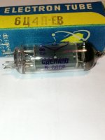
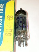
Hi hesener, the silver mica ones are like your sgm3 0,001uf, while the mating ones i used the russian k40-y9. Ilre made him build a specialized firm here in Italy. 12 ay7 tubes should arrive this week. I'm on vacation this week, see if I can make the electrical connections. For the straightening valve I took a Russian batch EZ90, let's see how they go.Hi Erman, nice work! Seems you are using the same silver mica caps in the RIAA that I used.... what coupling caps have you used?
I made all the changes you recommended. I have to solder the two wires on the relays as far as the phono section is concerned.
Hi thanks.
I made all the changes you recommended. I have to solder the two wires on the relays as far as the phono section is concerned.
Hi thanks.
Ciao hesener, quelli in mica d'argento sono come il tuo sgm3 0,001uf, mentre quelli di accoppiamento ho usato il russo k40-y9. Ilre gli fece costruire una ditta specializzata qui in Italia. 12 tubi ay7 dovrebbero arrivare questa settimana. Sono in vacanza questa settimana, vedo se riesco a fare i collegamenti elettrici. Per la valvola raddrizzatrice ho preso un lotto russo EZ90, vediamo come vanno.
Ho apportato tutte le modifiche che mi hai consigliato. Devo saldare i due fili sui relè per quanto riguarda la sezione fono.
Ciao grazie
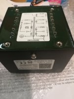
I had the transformer built on purpose by a specialized company here in ItalyCiao hesener, quelli in mica d'argento sono come il tuo sgm3 0,001uf, mentre quelli di accoppiamento ho usato il russo k40-y9. Ilre gli fece costruire una ditta specializzata qui in Italia. 12 tubi ay7 dovrebbero arrivare questa settimana. Sono in vacanza questa settimana, vedo se riesco a fare i collegamenti elettrici. Per la valvola raddrizzatrice ho preso un lotto russo EZ90, vediamo come vanno.
Ho apportato tutte le modifiche che mi hai consigliato. Devo saldare i due fili sui relè per quanto riguarda la sezione fono.
Ciao grazie.
Attachments
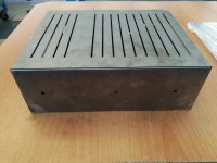
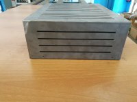
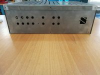
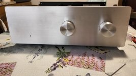
I designed the case, then I had a mechanical company our customer build it, laser drilling and sheet metal bending.Looks good! What kind of case is that?
Then painted.
Thank you
Attachments
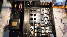
Thank You. It’s was a pandemic project. I got back into vinyl big time during the pandemic and after building a SS phono pre I remembered the issue of input capacitance causing HF boost in MM cartridges. When looking for a tube phono pre I stumbled across the K77 board and decided to order one. Many of the choices I made are the result of parts I had in stock. The capacitors in the RIAA are .01uf CDE 400v (the little yellow tubular ones). I got them from Parts Connexion here in Canada and they are supposed to have a vintage sound, whatever that means. I also used a 800v Mundorf .1uf gold Supreme that I had on hand. The RIAA is quite different than what the original was. The stock circuit would not work at all with the 6N1P. I got the RIAA within +- .2db with some tweaking. The interstage and output coupling caps are either Oblligato gold or CDE 940 series. I have 2 sets of main outputs and the phono outputs. I have small and large output caps connected to the 2 sets of main outs. I have a shorting switch on the back of the chassis that allows me to parallel the outputs or I can have the small/large caps on the outputs for use with mains/subwoofer biamping. I used Solens as power supply bypasses. The PS transformer is huge, perhaps 300w rated. Again, I had it on hand and the windings gave the right voltages. I also had the main chassis on hand. I repurposed it from another tube pre that I didn’t like, an Aikido that I built some years ago. I made the PS chassis from an old computer UPS enclosure cut down to the same height as the main chassis. I’ve been doing this DIY audio for a long time and have a good supply of “stuff” for use on my projects. Right now I am doing a muting mod and some other tweaks to the tube pre and I really miss it in my system.Looks like you spent a lot of work on your design, even with an offboard power supply, very nice!
What kind of RIAA and coupling caps did you use? (I noticed three different types....)
cool! I did find that the coupling caps play an important role in the sound, believe it or not....Thank You. It’s was a pandemic project. I got back into vinyl big time during the pandemic and after building a SS phono pre I remembered the issue of input capacitance causing HF boost in MM cartridges. When looking for a tube phono pre I stumbled across the K77 board and decided to order one. Many of the choices I made are the result of parts I had in stock. The capacitors in the RIAA are .01uf CDE 400v (the little yellow tubular ones). I got them from Parts Connexion here in Canada and they are supposed to have a vintage sound, whatever that means. I also used a 800v Mundorf .1uf gold Supreme that I had on hand. The RIAA is quite different than what the original was. The stock circuit would not work at all with the 6N1P. I got the RIAA within +- .2db with some tweaking. The interstage and output coupling caps are either Oblligato gold or CDE 940 series. I have 2 sets of main outputs and the phono outputs. I have small and large output caps connected to the 2 sets of main outs. I have a shorting switch on the back of the chassis that allows me to parallel the outputs or I can have the small/large caps on the outputs for use with mains/subwoofer biamping. I used Solens as power supply bypasses. The PS transformer is huge, perhaps 300w rated. Again, I had it on hand and the windings gave the right voltages. I also had the main chassis on hand. I repurposed it from another tube pre that I didn’t like, an Aikido that I built some years ago. I made the PS chassis from an old computer UPS enclosure cut down to the same height as the main chassis. I’ve been doing this DIY audio for a long time and have a good supply of “stuff” for use on my projects. Right now I am doing a muting mod and some other tweaks to the tube pre and I really miss it in my system.
Agreed. It’s hard to explain but I have made the same observation over the years.cool! I did find that the coupling caps play an important role in the sound, believe it or not....
Thank you, I thought it was fine as EZ90Ciao Ermanno! Lavoro decente. Fai attenzione, la piedinatura 6c4p è diversa da 6x4.
Hi hesener, I soldered the wires on the two relays, plus I made the other modifications you recommended, I hope they go well.Hi Erman, nice work! Seems you are using the same silver mica caps in the RIAA that I used.... what coupling caps have you used?
Attachments
Ciao hesener, ho saldato i fili dei due relè, in più ho apportato le altre modifiche da te consigliate, spero vadano bene.
Attachments
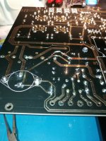

Keeping fingers crossed 😀Hi hesener, I soldered the wires on the two relays, plus I made the other modifications you recommended, I hope they go well.
- Home
- Amplifiers
- Tubes / Valves
- Kondo KSL-M77 phono preamp clone project