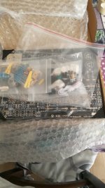
What exactly did they do wrong?Not you my friend, I'm talking about the guys who made the PCB and put the package together. They did great wrong. 🙂
Hi Hesener, pcb board arrived early.Can I use these capacitors I had in spare or are they too old? ThanksIn my case, I have 14V DC at the collector of the transistor and 12.8V on the heaters (I do not turn off the phono section, disabled this function in my build).
Remember you have to set the trimpot to maximum resistance so that the zener diode actually has a possibility to work.....
best greetings from the butcher 😀
Attachments
Much have been said, forum style (= chaotic). Here's a somewhat organized take:What exactly did they do wrong?
- Heater supply: the original sin, from Kondo-san, I believe: using a 2N3055 as a cap multiplier means the voltage can change significantly with the load. Plus, using the base current to set the output voltage is beyond crazy
- Switching on and off the phono section can change significantly the operating conditions: this, and everything below, are from the butchers
- The heater elevation is taken from where the ripple is the highest
- Shorting the phono output when not in use is beyond crazy
- The PCB is known to hum, due to the traces for the heaters
- The input traces are not optimum
- The PCB real estate is poorly managed: parts are very cramped in the RIAA section, where adjustments need to be made
- Poor choice of part: 10% polyester caps for the RIAA is beyond crazy
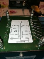
- The power transformer shipped with my kit has 6.3V/2A, 6.3V/2A, 5V/2A and 15V/2A: beyond crazy
- Anything I forgot?
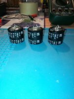
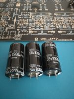
I also have these from 8200uf instead of 10000uf I was wondering if I could use them, I had ordered them by mistake. ThanksHi Hesener, pcb board arrived early.Can I use these capacitors I had in spare or are they too old? Thanks
Attachments
You can try to wake up slowly with an external adjustable power supply.Hi Hesener, pcb board arrived early.Can I use these capacitors I had in spare or are they too old? Thanks
Connect the power supply outputs to the condenser respecting the polarity and in parallel put a load (a resistance) and salts slowly with the voltage.
Watch out that if they really gone could burst so keep hands and face away.
Thanks!Much have been said, forum style (= chaotic). Here's a somewhat organized take:
- Heater supply: the original sin, from Kondo-san, I believe: using a 2N3055 as a cap multiplier means the voltage can change significantly with the load. Plus, using the base current to set the output voltage is beyond crazy
- Switching on and off the phono section can change significantly the operating conditions: this, and everything below, are from the butchers
- The heater elevation is taken from where the ripple is the highest
- Shorting the phono output when not in use is beyond crazy
- The PCB is known to hum, due to the traces for the heaters
- The input traces are not optimum
- The PCB real estate is poorly managed: parts are very cramped in the RIAA section, where adjustments need to be made
- Poor choice of part: 10% polyester caps for the RIAA is beyond crazy
- The power transformer shipped with my kit has 6.3V/2A, 6.3V/2A, 5V/2A and 15V/2A: beyond crazy
- Anything I forgot?
Most of these issues have been addressed in this tread, as you say. I have done the Darlington/Zener-diode modification and modified the RIAA-section (as specified by Hesener). And the preamp is now silent and sounds (thankfully) very good.
I wonder, if I want to keep the phono section on all the time. What do I need to do?
Hi zung, I think your list is pretty good. Personally I was most frustrated by the RIAA section, but thats not complicated to improve, fortunately. I would also add that switching the phono tubes on and off will shorten their lifetime.Much have been said, forum style (= chaotic). Here's a somewhat organized take:
- Heater supply: the original sin, from Kondo-san, I believe: using a 2N3055 as a cap multiplier means the voltage can change significantly with the load. Plus, using the base current to set the output voltage is beyond crazy
- Switching on and off the phono section can change significantly the operating conditions: this, and everything below, are from the butchers
- The heater elevation is taken from where the ripple is the highest
- Shorting the phono output when not in use is beyond crazy
- The PCB is known to hum, due to the traces for the heaters
- The input traces are not optimum
- The PCB real estate is poorly managed: parts are very cramped in the RIAA section, where adjustments need to be made
- Poor choice of part: 10% polyester caps for the RIAA is beyond crazy
- The power transformer shipped with my kit has 6.3V/2A, 6.3V/2A, 5V/2A and 15V/2A: beyond crazy
- Anything I forgot?
I am not sure if Kondo-san intended to use grid biasing in the input stage of the phono section, but I am not a fan, as this (as well as a few other design choices you mentioned) is making operation rely on parasitic device characteristics, which are neither guaranted nor measured, and will drift over time. Rather prefer to have bias conditions locked in.
Not all is bad, though - the PCB is working and an OK starting point, from where to optimize, and learn in the process. Mind you, maybe the guys doing the PCB are listening in here, and may improve their design in the future?
There is one of the black (in my case) relays that connects the heater supply of the phono section. Simply follow the traces and solder a short wire across the relay contact. The relay may still be switching but the heaters will be on all the time. Easy to undo if you want to. Unfortunately I am not at home so I don 't have a picture to show at hand.....Thanks!
Most of these issues have been addressed in this tread, as you say. I have done the Darlington/Zener-diode modification and modified the RIAA-section (as specified by Hesener). And the preamp is now silent and sounds (thankfully) very good.
I wonder, if I want to keep the phono section on all the time. What do I need to do?
There is a second relay for the high voltage supply, I left that one untouched. In my experience, it is the heater turn-on / off that stresses the tubes the most, and that is resolved with the first mod.
Happy that the zener mod is working for you!
You should deal with this one too because it changes the high voltage, and therefore the operating conditions..... There is a second relay for the high voltage supply, I left that one untouched...
Shorting is OK; me, I removed the relays completely, but it's more work.
Does anyone have a good supply of reasonably priced 12AY7/6072A tubes? I'd sure like to pick up a minimum of four and get that many reject 12AU7's out of my KSL. But the prices of them these days!
However I did go and buy an ALPS volume pot after discovering my current one wasn't doing it for me. It'll be a little while as it makes its way out of Germany.
But I do wonder about the 12AY7s. My Amperex and Mullard12AU7's sound perfectly fine to me..... will the 12AY7s sound..... better?
However I did go and buy an ALPS volume pot after discovering my current one wasn't doing it for me. It'll be a little while as it makes its way out of Germany.
But I do wonder about the 12AY7s. My Amperex and Mullard12AU7's sound perfectly fine to me..... will the 12AY7s sound..... better?
C'è uno dei relè neri (nel mio caso) che collega l'alimentazione del riscaldatore della sezione fono. Segui semplicemente le tracce e salda un filo corto attraverso il contatto del relè. Il relè potrebbe ancora essere commutato ma i riscaldatori saranno sempre accesi. Facile da annullare se lo desideri. Purtroppo non sono in casa quindi non ho una foto da mostrare a portata di mano.....
C'è un secondo relè per l'alimentazione ad alta tensione, quello l'ho lasciato intatto. Nella mia esperienza è l'accensione/spegnimento del riscaldatore che stressa di più i tubi, e che si risolve con la prima mod.
Felice che la mod zener funzioni
Attachments

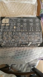
Hi everyone, I started welding.
Do all six relays need to be soldered?
I saw that there is a modification, if I'm not mistaken the phono relay, thank you.
Do all six relays need to be soldered?
I saw that there is a modification, if I'm not mistaken the phono relay, thank you.
Yes all 6 relays need to be soldered in. But the most difficult soldering job which must be done, is soldering in the ribbon wire connectors. It was at this point where I decided the soldering was beyond my capabilities and for $140, I bought an assembled PCB.
I decided to put the 6X5 back in after I found a source for 7-pin ceramic sockets. The arraignment makes B+ much more steady and predictable.. Besides the cheap 7-pin plastic socket which came with the PCB is pretty trashy and doesnt' belong.
I also put my new ALPS Volume Pot in!! Now that thing is seriously nice. One could even say that the ALPS pot correct many of the problems that cheaper POTs have.
And that's it! I am now a proud owner of a fantastic, and fully functional and fully functional KSL-M77 preamp! I have ben at this now for 17 months and its FINALLY done!!
Except for one thing (Its always something) .. The TUBES!! I have three 12AY7s and five 12AU7s. I'll put another five 12AY7s some day...
.
Hi, I'm almost finished soldering the board, I miss the container that I have to make a company I know, and the Eizz potentiometer that will arrive shortly, and then the valves.
Post some photos.
Bye thank you.
Hi, I'm almost finished soldering the board, I miss the container that I have to make a company I know, and the Eizz potentiometer that will arrive shortly, and then the valves.
Post some photos.
Bye thank you.
Attachments

Great! Let us know your sound impressions , it will probably need a few weeks of running in thoughYes all 6 relays need to be soldered in. But the most difficult soldering job which must be done, is soldering in the ribbon wire connectors. It was at this point where I decided the soldering was beyond my capabilities and for $140, I bought an assembled PCB.
I decided to put the 6X5 back in after I found a source for 7-pin ceramic sockets. The arraignment makes B+ much more steady and predictable.. Besides the cheap 7-pin plastic socket which came with the PCB is pretty trashy and doesnt' belong.
I also put my new ALPS Volume Pot in!! Now that thing is seriously nice. One could even say that the ALPS pot correct many of the problems that cheaper POTs have.
And that's it! I am now a proud owner of a fantastic, and fully functional and fully functional KSL-M77 preamp! I have ben at this now for 17 months and its FINALLY done!!
Except for one thing (Its always something) .. The TUBES!! I have three 12AY7s and five 12AU7s. I'll put another five 12AY7s some day...
Nothing wrong with a little performance review now 🙂
First of all, the hardware variations off the common baseline:
1) Tube compliment
a. Three JJ 12AY7s
b. Five assorted 12AU7s (Mullard, Amperex) I hope to get matching 12AY7/6072A tubes soon
c. One 6X4 Rectifier, ceramic socket
2) 20H Chicago Transformer Choke - in standard location
3) All Rhodium Plated RCA Jacks
4) All mil-spec silver plated wires
5) MKP 'Audiophiler' line amp coupling caps
NOTE: I recommend getting the assembled PCB with all components installed simply because of convenience and unless you're an EXPERT solderer, not having the need to solder the ribbon cable sockets to the PCB. I thought I was a good solderer but I was wrong. I bought the $140 PCB after I destroyed my first one.
This project took just over one year to complete but it was worth it. I have tried many preamps with my all tube custom power amp, my turntable and
CD player and they ALL had something wrong with them... from hum to lack of spectral experience..
But the KSL-M77 is different. Not to say I won't find its flaw(s) but as of now, it is the only preamp of not sitting on my parting out table. Lets discuss its sound. The M77 puts out just the right amount of bass to give the overall pace of the music - not boomy and not thin and veiled. Midrange is real with a very wide stage - quite awesome, actually. And chimes are a good representation of the higher frequencies - another good show.
I used to have a set of Bohlender-Graebener ribbons with a custom made Rudi Blondia active crossover. Those were hard to beat BUT they were 10x the cost of my current setup too! Of course Speakers will make or break the setup and I am currently using ProAC Tablettes.
All in all I am quite satisfied.
I'll follow up in 6 months or so.
Very nice, seems you are quite satisfied! The midrange is special on these, mine gives a certain "inner light" or "shine" and - while it may well be not real - is so nice to listen to..... Seems your's is similar?
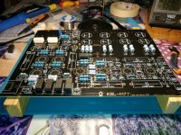
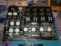
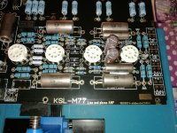
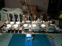
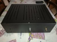
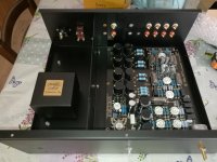
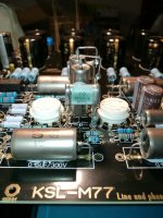
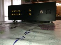
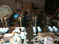
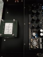
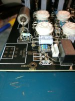
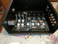
Hello everyone, I present to you my almost finished work.
Attachments
-
 IMG_20220801_011050.jpg430.6 KB · Views: 228
 -
 IMG_20220807_190956.jpg331.5 KB · Views: 213
 -
 IMG_20220807_180430.jpg440.9 KB · Views: 208
 -
 IMG_20220801_225806.jpg408.1 KB · Views: 213
 -
 IMG_20220808_224615.jpg287.7 KB · Views: 218
 -
 IMG_20220807_191043.jpg297.9 KB · Views: 207
 -
 IMG_20220801_011109.jpg322.4 KB · Views: 194
 -
 IMG_20220807_180913.jpg271.9 KB · Views: 205
 -
 IMG_20220801_231827.jpg362.7 KB · Views: 222
 -
 IMG_20220801_225851.jpg453.2 KB · Views: 228
 -
 IMG_20220807_180656.jpg396.2 KB · Views: 238
- Home
- Amplifiers
- Tubes / Valves
- Kondo KSL-M77 phono preamp clone project