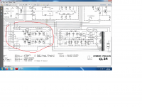
I would think that with fixed values of 300k inputs resistor, 1Meg load resistor and 1n / 10n capacitors the values for the other 2 resistors (30k and 33k in original circuit) should be fix as well - or not?
yes exactly. and if you do the math, or simulate, it is all correct except the 33k resistor which really should be 50k. So, this resistor needs changing.
Plus, if you want to add the "neumann" constant, you need to add the additional 10k resistor. It will give a boost of 2-3dB at 20kHz. This topic is hotly debated and I am not going to add any opinion here, only that to my and my friends ears, it sounds better if you add this in.
Zung is very correct, and as I mentioned in my previous post, please do spend as much time and effort as possible for you to make sure the absolute value of the components is good (better than 1%, if possible) and also the channel-to-channel variation is as small as possible, for identical values in both channels. This will much improve the "imaging" and tonality of the phono stage.
And, as mentioned, good quality components really pay off here 😀
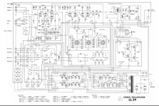
Just to clarify - 10nF capacitor assembled in your M77 is the one which shows 1 nF in the schematic? (attached 0.001)
I think the 10nF (as per the PCB) which in his kit is 1nF (wrongly) is not the RIAA cap. It is the cap from grid to ground of the input cascode tube.
It will establish a lowpass filter with the 10MOhm resistor for grid leak bias, time constant t = R*C = 10MOhm * 10nF = 0.1s, corresponding to 1.4Hz (roughly). Here, 1nF will give a lower corner frequency of 14Hz, still ok but not as low as the original.
So, using 10nF is best I think, smaller values will cut into the audio band at some point, (much) larger values will eventually increase the startup time.
unless I got it completely wrong 😀
yes exactly. and if you do the math, or simulate, it is all correct except the 33k resistor which really should be 50k.

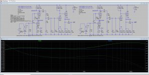
Here's what the Sim gives: green: 33K, blue: 50K. About +/-0.25dB. If you want better, you can, just invest a lot of time.
Attachments
Some people apparently have issues with hum/noise because of the heater power supply, and some suggest adding a regulated heater power supply. An example is mentioned here: This guide is to help you build the DOUK KSL-M77 Preamp clone kit.
What do you think about this? Is it a worthwhile upgrade?
What do you think about this? Is it a worthwhile upgrade?
In my build I can measure the hum but when listening it is not really apparent.
Measured the heater supply and also the HV supply, and it seems that both are contributing to output hum.
So this upgrade may actually be worthwhile, I am considering it too. Please note that the heater voltage is not at ground potential but at roughly 2/3 of B+ , same for the relay supply. So please do not connect any external regulator to ground, but only to the capacitor connections as mentioned in this other build guide.
Fillament lifting or capacitor multiplier are better than regulators on fillament.Capacitor multipliers work in luman , they should work everywhere.I'd use a darlington transistor there as today they are largely available.
Attachments
this clone also uses a cap multiplier with the big bipolar transistor. It is not very effective, though. The trimpot is used to adjust the tube heater voltage a little bit, and obviously affects the noise suppression capability of this circuit.
Using an external regulator, in combination with the filament lifting already implemented on this PCB, should definitely reduce the hum.
quick sim shows -43dB at 50Hz as per attached picture, not great but at least some help. (I used ESR of 0.1Ohm for both caps)
What is a little worrysome is the current in the trimpot (30mA), caused by the not-so-great current gain of this transistor. Power dissipation in the trimpot is quite high, albeit still in acceptable levels, but I wouldnt be surprised if it fails after some time.
Attachments

Last edited:
Luxman is using two darlington transistors for the same number of tube fillaments as ksl m77 ...you could use triplets if doubtful 🙂 , but transitors with hfe=15000 are easy to find.I can only tell i have built a Luxman clone already with even higher fillament current demands(12bh7 instead of 12au7)and the multipliers work very well.
Last edited:
Here's what the Sim gives: green: 33K, blue: 50K. About +/-0.25dB. If you want better, you can, just invest a lot of time.
Fantastic, thank you both! I'm going to order some good quality resistors and caps and repalce all 300k, 10k, 30k, 50k and 1n, 10n parts in the phono signal path 😉
Luxman is using two darlington transistors for the same number of tube fillaments as ksl m77 ...you could use triplets if doubtful 🙂 , but transitors with hfe=15000 are easy to find.I can only tell i have built a Luxman clone already with even higher fillament current demands(12bh7 instead of 12au7)and the multipliers work very well.
Good point. I simulated with a darlington configuration, and it reduces noise by >25dB, easy enough modification. Will try it on my preamp and let you guys know!
So, here is the deal: I used a BC337-40 in darlington configuration with the built-in 2N3055, and 100Hz noise reduced by 17dB, 200Hz noise reduced by 8dB.
So, the improvement is there although not massive. For fun, I simulated a little regulator with the TL431 and that should be much better. not sure when I have the time to test....
So, the improvement is there although not massive. For fun, I simulated a little regulator with the TL431 and that should be much better. not sure when I have the time to test....
yes, the big caps on the output are not always helpful in a cap multiplier. But I didnt want to change too much, just see what happens when I make a little addition....
Essentially, the heater circuit is very simple - instead of connecting the AC voltage directly, its rectified and followed by cap multiplier. I noticed however that it is not very gentle to the tubes - adjusting range is small and depends on a lot of factors. When only 4 tubes are in I measured a voltage of 13.3V, too much. So, next step will be to try a regulator but that may take a few days.
Essentially, the heater circuit is very simple - instead of connecting the AC voltage directly, its rectified and followed by cap multiplier. I noticed however that it is not very gentle to the tubes - adjusting range is small and depends on a lot of factors. When only 4 tubes are in I measured a voltage of 13.3V, too much. So, next step will be to try a regulator but that may take a few days.
The higher the transistor's hfe, the more stable the hfe, but you should move the 10kuf at the input and the 4700u at the output.whhy don't you just replicate luxman's cap multiplier? There's no need to be original...
So, here is the deal: I used a BC337-40 in darlington configuration with the built-in 2N3055, and 100Hz noise reduced by 17dB, 200Hz noise reduced by 8dB.
Adding a 14V zener diode to this circuit reduced the noise by another 20dB plus.... And, the heater voltage is now 12.6V rock stable.
I think it is an easy modification: Put a darlington transistor in place of the 2N3055, e.g. the MJ3000 (plenty available in the bay), put the trimpot to maximum resistance, and add a zener diode 14V in parallel to the 4700uF cap. (I used a 13V zener diode plus a 1n4148 in series, because that's what I had 😀). Works like a charm!
(and it now pretty much resembles the Luxman circuit 😀)
Last edited:
Is this modification as effective as an external regulator? I suppose you soldered the zener diode on the back of the PCB. Can you post a photo?
Sorry I havent tried an external regulator but I think they are quite similar, with remaining ripple on the heaters in the mV range. Yes, the zener is on the back of the PCB, forgot to take a photo - will do tomorrow. But its very easy, just solder across the capacitor terminals (with the bar of the zener diode to the "+" of the cap).
- Home
- Amplifiers
- Tubes / Valves
- Kondo KSL-M77 phono preamp clone project