M77 heater mod
So, here you go, please check the attached picture. It has the new schematic and shows the connections as well.
Components you will need:
1x BC337-40 or another suitable small signal bipolar NPN transistor
1x Zener diode 14V (please note I used a 13V zener plus a regular diode in series)
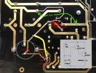
First, you need to make three cuts in the PCB at the designated locations .
Then, add the two components and the wire connection (yellow).
Third, check the heater voltage at the designated location on the topside (voltage given in green). You should be up and running at this point!
This mod may not be the most exciting one, but it makes use of all the existing components in place, and is doable with a minimum of modifications.
So, here you go, please check the attached picture. It has the new schematic and shows the connections as well.
Components you will need:
1x BC337-40 or another suitable small signal bipolar NPN transistor
1x Zener diode 14V (please note I used a 13V zener plus a regular diode in series)
First, you need to make three cuts in the PCB at the designated locations .
Then, add the two components and the wire connection (yellow).
Third, check the heater voltage at the designated location on the topside (voltage given in green). You should be up and running at this point!
This mod may not be the most exciting one, but it makes use of all the existing components in place, and is doable with a minimum of modifications.
Attachments
Last edited:
Great! Seems like a simple modification. I don't have a BC337, but found a bag of BC548. Can I use one of those?
An alternative to an extra resistor is to put in a MJ3000 instead of the 2N3055? A bit more aesthetically pleasing (which is silly, but ...)
BC548 should be ok as well.
Please note that the MJ3000 is a darlington transistor, so it already has two bipolar transistors inside, this is what the circuit with the BC337 and 2N3055 is doing. If you use a MJ3000, you do no longer need an additional bipolar transistor. This mod is done all under the PCB so not visible from the top 😀
If you use a power darlington such as the MJ3000, simply replace the 2N3055 with it and add the zener diode. Remember to put the trimpot to maximum resistance before turn-on (else the zener diode might blow up).
Great, thanks! I think I'll go for the MJ3000 transistor. Easy to find on eBay as you said. Also less work, and I don't have to cut any traces.
M77 heater mod simplified
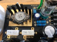
Another thought this morning under the shower - what if that scrap box had an old, unused darlington transistor? So I went and checked..... And yes, there was an old, unloved MJ3001 with cables from some previous experiment...... In it went.....
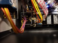
Check out the pictures for the mod, essentially all you have to do is
- Replace the 2N3055 with a good, sturdy darlington (MJ3000 or MJ3001 will do fine), make sure to apply thermal grease as it will get a little hotter than before
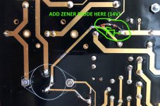
- Add a 14V zener diode on the bottom side, as indicated
Tried it just now, works like a charm 😀
Another thought this morning under the shower - what if that scrap box had an old, unused darlington transistor? So I went and checked..... And yes, there was an old, unloved MJ3001 with cables from some previous experiment...... In it went.....
Check out the pictures for the mod, essentially all you have to do is
- Replace the 2N3055 with a good, sturdy darlington (MJ3000 or MJ3001 will do fine), make sure to apply thermal grease as it will get a little hotter than before
- Add a 14V zener diode on the bottom side, as indicated
Tried it just now, works like a charm 😀
Attachments
Hi everyone,
I turned on the M77 for the first time today. No smoke, and it seems to work! Two problems:
Thanks,
Trond
I turned on the M77 for the first time today. No smoke, and it seems to work! Two problems:
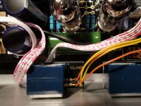
- The balance control doesn't work as expected, as nothing much happens when I turn it. I assume I have wired it wrong. See photos. I need advise about how to correctly wire this.
- The is quite a loud hiss. Ground loop perhaps?
Thanks,
Trond
Attachments
Member
Joined 2009
Paid Member
Hiss is unlikely a ground loop (that would be hum). I had badd hiss from a tube phono once and abandoned the project before solving it. I remember it was noise coming from the tube. I have read that some tubes can be v noisy. I had bought my tubes from eBay, a small number of Russian frame grid triodes and possibly just a noisy batch.
Parasitic oscillation is another possible source of noise.
Parasitic oscillation is another possible source of noise.
if you have access to an oscilloscope, try connecting it to the output to see if there is high frequency oscillations there.
Is the noise coming from the phono only, or the line stage as well? And if it is phono, can you try and short-circuit the inputs to see if the noise persists?
Is the noise coming from the phono only, or the line stage as well? And if it is phono, can you try and short-circuit the inputs to see if the noise persists?
Thanks! Problem 1. is just that the pcb is intended for an antilog potentiometer, I think.
Hum is probably the right word. It's silent when the volume is at the lowest, and is increasing when i turn the volume up. The hum also varies slightly when I touch the chassis and the tubes. I'll experiment a little and report back!
Hum is probably the right word. It's silent when the volume is at the lowest, and is increasing when i turn the volume up. The hum also varies slightly when I touch the chassis and the tubes. I'll experiment a little and report back!
Member
Joined 2009
Paid Member
Simple solution to the hum problem. It disappeared when I put a wire between the chassis and ground on the circuit board. The preamp part seem very quiet. There is some hum in the riaa part (with shorted inputs), but I haven't tested it with an actual turntable yet, so I don't know how noticeable it will be.
Member
Joined 2009
Paid Member
Thanks! Problem 1. is just that the pcb is intended for an antilog potentiometer, I think.
Hum is probably the right word. It's silent when the volume is at the lowest, and is increasing when i turn the volume up. The hum also varies slightly when I touch the chassis and the tubes. I'll experiment a little and report back!
Antilog...... It´s called linear as in contrast to logarithmic.
Volume is (mostly) always log.
Balance is always linear.
Antilog...... It´s called linear as in contrast to logarithmic.
Volume is (mostly) always log.
Balance is always linear.
You are of course right! Learning something new every day. I was a bit quick and thought antilog meant something else. Electronics isn't exactly my field of expertise.
But I actually have a linear pot in there now, and it doesn't work. It only changes the volume a tiny bit equally on both channels. And I don't understand how it's supposed to work the way it is wired.
I hope someone has connected a balance potentiometer to this board. Very interested in knowing what they did to make it work.
I connected the M77 to my stereo system today, driving my newly built EL34 Baby Huey amp and Frugel-Horn speakers. The hum in the phono preamplifier is hardly noticeable.
The most important thing is that it sounds really good! I'm very pleased with it, and I think this preamp will see a lot of use.
I replaced the filter capacitors, coupling capacitors and some resistors in the kit as per advice in this thread. Instead of a balance potentiometer, I'll may instead use two mono pots.
I hope someone has connected a balance potentiometer to this board. Very interested in knowing what they did to make it work.
I bridged mine, sorry 😀
I connected the M77 to my stereo system today, driving my newly built EL34 Baby Huey amp and Frugel-Horn speakers. The hum in the phono preamplifier is hardly noticeable.
The most important thing is that it sounds really good! I'm very pleased with it, and I think this preamp will see a lot of use.
I replaced the filter capacitors, coupling capacitors and some resistors in the kit as per advice in this thread. Instead of a balance potentiometer, I'll may instead use two mono pots.
Excellent! Mine needed a good 20hrs to get going, still improving a little bit after 100hrs or so . Enjoy!
- Home
- Amplifiers
- Tubes / Valves
- Kondo KSL-M77 phono preamp clone project