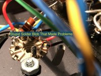
Found it!
I started wiggling stuff and found that when I wiggled the plate connection to the OPT the resistance started to jump around. Turns out a Stupid Solder Blob That Made Problems was the culprit.
Finally got all the solder wicked away and am beginning to hook everything back up for testing.
FAULT #1 ELIMINATED.
KOFI
Attachments
Ah ha! Good catch.
I haven't thought it through too carefully, but that may be the reason for the differing readings-to-ground for your screen taps. You were reading through varying lengths of windings. With just one plate connection "shorted" to ground, the problem would show up on both OTs since the B+ connection is common to both.
I'm sure you'll look carefully, and take the readings again, but where there is one solder blob there may be...
Last edited:
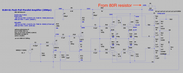
The 80R dropping resistor in your power supply will be dissipating ~10W, so you probably want to use at least a 30W chassis mount or maybe (3) 250R-10W in parallel.
Funny Kofi Story:
So, I wasn't getting any output from one of the channels initially. Looked like signal was going in but not getting out. Couple hours roll by and I can't for the life of me...
Then I went to swap the outputs to see and I noticed that I DID NOT STRIP THE PLASTIC OFF THE SPEAKER CABLES.
Yikes, Kofi. That was a bad one.
Kofi
Funny Kofi Story:
So, I wasn't getting any output from one of the channels initially. Looked like signal was going in but not getting out. Couple hours roll by and I can't for the life of me...
Then I went to swap the outputs to see and I noticed that I DID NOT STRIP THE PLASTIC OFF THE SPEAKER CABLES.
Yikes, Kofi. That was a bad one.
Kofi
😀
OK-- question for the council:
So, I need to drop about 30 - 50 volts to hit a supply voltage of around 300VDC to 320VDC and I'm running into some space restrictions in the chassis.
I'm sure I could drop the B+ by lowering the first cap to around 10uF or so (guessing at the value for the moment), but would removing the final filter cap be an option (see schematics attached)?
Thoughts?
Kofi
Attachments
I'd leave the final cap in place. You could reduce the first capacitor to ~100uF to minimize the initial turn-on surge, and use something like 25R-10W in each leg of the PT secondary before the rectifier.
If you are 350V and under and no signs of red plating I would not worry about it, the supply voltage will likely sag a bit at higher powers. Otherwise I would recommend a power resistor in series with the HV secondary as already suggested.
Don't under any circumstances remove that last filter cap unless you want lots of cross-talk and generally poor performance.
Most of the antique 6BQ5 amps I have worked on were between 360 - 400V on the plates with a nominal 117VAC line (variac) and the only tubes that seem to have a problem with this are current production JJs IMVLE.. HH Scott stuff with 7189As were over 400V.
Thanks, guys. Appreciate the feedback on this.
Looks like the supply is delivering around 380VDC before the final resistor / cap, which is much higher than I expected. I'm guessing my line voltage is a little high.
It looks like the 100R (4 x 400R in parallel) dropping resistor I fitted is dropping 36VDC, so total current draw is 360mA. After the final resistor / cap in the supply, I'm getting 340VDC at the center tap of the OPT.
I'll need to find a way to add some turret boards to give me a few more solder points for the final resistor / cap combo.
Also-- I found that the 1A slo-blo fuse was blowing after a few minutes of operation. I replaced it with a 2A, but I usually try to keep it at 1A. I'm assuming the additional current draw may be heating up the fuse over time and causing it to blow.
Does that sound correct?
Kofi
You need a fuse larger than 1A.
360mA @ 340VDC is 122.4W, so you are drawing a little more than 1A on the primary side.
A 2A fuse is OK.
360mA @ 340VDC is 122.4W, so you are drawing a little more than 1A on the primary side.
A 2A fuse is OK.
I'd leave the final cap in place. You could reduce the first capacitor to ~100uF to minimize the initial turn-on surge, and use something like 25R-10W in each leg of the PT secondary before the rectifier.
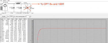
Hmm.. I believe someone mentioned this before but I blew by it.
So, I modeled another supply in PSUD, adding an additional 50R of source resistance to the power transformer to mimic the impact of the 2x25R resistors in each leg of the AC before the rectifier.
Does this look correct?
Kofi
Attachments
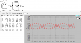
Yes, but you should leave the last RC section in place as was mentioned. Ripple is significantly reduced.
Yes, but you should leave the last RC section in place as was mentioned. Ripple is significantly reduced.
Boom.
Attachments
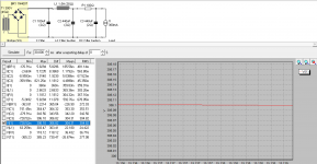
Looks good. Also I see that you did not have to use as much series resistance on the PT secondary. Should work out great. If needed, the final R could be adjusted slightly to get right where you want to be.
Thanks. Yep-- I think I'll have to mess with the resistance a bit to get it dialed in.
Curious-- why would I only need a 10W before the rectifier when I would require over 20W for the final R?
Always learning here.
Kofi
Curious-- why would I only need a 10W before the rectifier when I would require over 20W for the final R?
Always learning here.
Kofi
I should not have posted late (for me) last night and I wasn't really thinking this morning.
You were correct with your model in post #134. If you take the whole supply into account there is plenty of filtering and all of the voltage adjustment can be done with the series resistors on the PT. And, you get rid of the big power soaking resistor. The power stage ripple should cancel in the OT.
I hope I didn't cause you too much trouble with my errant post.
Attachments
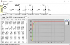
No problem at all. This helps me quite a bit, actually, since I should now be able to mount the series resistors on the chassis and avoid cramming more components into the existing turrets.
Thanks so much for all your help!
Kofi
Thanks so much for all your help!
Kofi
- Home
- Amplifiers
- Tubes / Valves
- Kofi Annan in: "Tube Amp for Multi-Way Speakers"