Oh boy... I think I found the problem. Can you guys keep a secret?
It probably is a case of PEBCAK.
At home I normally start the python program using putty on my laptop and then use the web interface on my phone to start the measurements.
In the barn I use my phone also for starting the program (using JuiceSSH). Works great. I have a small dedicated wifi router near the scanner so even though I don't have internet connection, I do have a network and I can connect to the pi in the normal way (ssh over network).
As long as I'm nearby listening whether it's still running everything is running smoothly. As soon as I get in my car and return home I loose my wifi connection to the dedicated router. JuiceSSH looses the connection, terminal closes and.... processes started in that terminal are stopped.
I can trigger it at home by turning wifi off on my phone. Placing an & after the command to start python seems indeed to be the solution.
You could also make a screen
ps. web is pain nowadays, clicked perhaps ten links on search engine results before found a page that explains screen where the cookies and subscriptions and other popups was relatively easy to deny.
ps. web is pain nowadays, clicked perhaps ten links on search engine results before found a page that explains screen where the cookies and subscriptions and other popups was relatively easy to deny.
Last edited:
I see that you are blessed as I am with absent minded retardation of useful thought. Glad you figured it out. I do this so often I have no more hair from the forehead smacks. ☺️Oh boy... I think I found the problem. Can you guys keep a secret?
It probably is a case of PEBCAK.
At home I normally start the python program using putty on my laptop and then use the web interface on my phone to start the measurements.
In the barn I use my phone also for starting the program (using JuiceSSH). Works great. I have a small dedicated wifi router near the scanner so even though I don't have internet connection, I do have a network and I can connect to the pi in the normal way (ssh over network).
As long as I'm nearby listening whether it's still running everything is running smoothly. As soon as I get in my car and return home I loose my wifi connection to the dedicated router. JuiceSSH looses the connection, terminal closes and.... processes started in that terminal are stopped.
I can trigger it at home by turning wifi off on my phone. Placing an & after the command to start python seems indeed to be the solution.
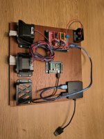
I'm trying to improve the cable management for the cables going to the movable arm. Currently I feed them through the center hole:
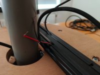
So the 4 cables from the arm are going between the stationary PVC pipe/stand and the rotating wooden table. It's not really bad, but it not really great either.
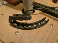
I've been contemplating a cable guide:

I probably need another plate over the beam to have a nice flat area for the cable guide to rest on. I'm not convinced this is going to work though. The guide has some edges that it can get itself stuck to.
Let's brainstorm a bit:
No management, just have them dangling from the end of the measurement arm. Might actually work fine for the barn setup; probably not as a table top device.
Not going through the moving wooden table, but around it. I don't see this as a possibility as both the counterweight and the arm are passing over/through them. Maybe if I get rid of the counterweight or place them otherwise.
Do you guys have any ideas?
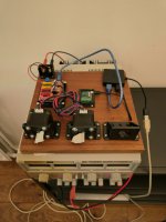
btw I improved the waveguide stand considerably:
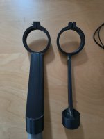
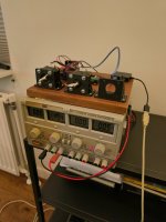
And I guess you guys hadn't seen the barn setup yet:
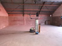

So the 4 cables from the arm are going between the stationary PVC pipe/stand and the rotating wooden table. It's not really bad, but it not really great either.
I've been contemplating a cable guide:

I probably need another plate over the beam to have a nice flat area for the cable guide to rest on. I'm not convinced this is going to work though. The guide has some edges that it can get itself stuck to.
Let's brainstorm a bit:
No management, just have them dangling from the end of the measurement arm. Might actually work fine for the barn setup; probably not as a table top device.
Not going through the moving wooden table, but around it. I don't see this as a possibility as both the counterweight and the arm are passing over/through them. Maybe if I get rid of the counterweight or place them otherwise.
Do you guys have any ideas?
btw I improved the waveguide stand considerably:

And I guess you guys hadn't seen the barn setup yet:

A tip about your cabling Tom;
with all the loose wires it is a bit of an " EMC nightmare" and with all the nasty pulses from the servos it will most likely cause instabillity problems with the microcontrollers.
Make sure that ALL signal paths (psu voltages and control voltages) have there own ground wire which runs directly next to the signal wire.
A good cheap solution for this is to use twisted wire pairs from a CAT cable.
place all your control board on a massive groundplane (for instance coppertape on you current wooden(?) board and connect ALL grounds ( so from all boards and all servos etc. ) DIRECTLY to this plane, as closely to the position where tje signal wire connects to a board.
This will certainly help with stabillity issues 🙂
this very well explained tutorial might help get some insight in proper grounding;
I've seen that video. I've also probed around with my oscilloscope a bit. The arduino is controlled using a USB cable. The microphone cable is also running along the moving arm. Then there is the power for the steppers (via the arduino cnc shield). Each is routed through its own 'cavity' in the aluminum extrusion. I have thought about replacing the two loose power cables by a zipcord. The tic and arduino are separated roughly a meter apart. So it's not a centrallised PCB where one can simply follow the rules above. The setup is a bit too noisy to my liking, but I don't have stability issues. I guess I will look into it sometime later, once the bigger wrinkles have been ironed out.
So, anyone any ideas about the cable management wrt the rotational motion of the arm?
Here is something as an inspiration:
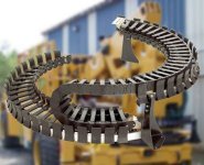
So, anyone any ideas about the cable management wrt the rotational motion of the arm?
Here is something as an inspiration:

Last edited:
have you tried tying the cables together with something to allow them to act as one stiffer cable? Either string or plastic ties. LIke you see in millspec electronics.I'm trying to improve the cable management for the cables going to the movable arm. Currently I feed them through the center hole:
View attachment 1373124
So the 4 cables from the arm are going between the stationary PVC pipe/stand and the rotating wooden table. It's not really bad, but it not really great either.
I've been contemplating a cable guide:
View attachment 1373125
I probably need another plate over the beam to have a nice flat area for the cable guide to rest on. I'm not convinced this is going to work though. The guide has some edges that it can get itself stuck to.
Let's brainstorm a bit:
No management, just have them dangling from the end of the measurement arm. Might actually work fine for the barn setup; probably not as a table top device.
Not going through the moving wooden table, but around it. I don't see this as a possibility as both the counterweight and the arm are passing over/through them. Maybe if I get rid of the counterweight or place them otherwise.
Do you guys have any ideas?
btw I improved the waveguide stand considerably:
View attachment 1373127
And I guess you guys hadn't seen the barn setup yet:
View attachment 1373128
Love the barn!
OK I think that I missed the point of the cabling question. Your mic cable goes through the extrusions up to the mic. No problem there. Ideally for least rotation they would pass through the center of that vertical pipe in the middle that supports the loudspeaker turntable. Then you have the minimum amount of rotational stresses on the wire. I used to work with mic cables a lot. And over time they do indeed break from use. Generally from the shield on into the interior. Shield problems start first, and then the mics cable is not so useful. Like that cable chain.
So do I have the wiring concept a little better understood?
So do I have the wiring concept a little better understood?
I don't know what you thought before, so I don't know if it's better. But I agree with what you say.
The optimal way from the center of the vertical pipe to the extrusion would be a straight line. Which would cut the pipe in two for a full rotation. Not ideal 😉
So, what is the solution?
The optimal way from the center of the vertical pipe to the extrusion would be a straight line. Which would cut the pipe in two for a full rotation. Not ideal 😉
So, what is the solution?
Vertical pipe is stationary. Plywood disc and extrusion arm rotate. This is the image I have ay the moment. Agreed a cut through 50% of the pipe is not exactly optimal. And you are looking to route two power leads that fit the Loudspeaker?
Loudspeaker is stationary. Like the tic controller to rotate the table.
Rotating:
Mic cable, Arduino usb cable and Arduino cnc shield power cable.
Rotating:
Mic cable, Arduino usb cable and Arduino cnc shield power cable.
Just an idea, use of truss for the system??? https://www.diyaudio.com/community/threads/vituixcad.307910/post-7833986
Actually i am thinking for the beam holding the mic frame, in combination with a 90 degree corner, which would be instead of the pvc pipe. This corner to be rotatinf around the centerpipe. It is a quite stiff yet Light construction. And could be made demontabele for transport or storage.
I was using the klippel construction as a backdrop in my thinking. If one wants a smaller max diameter it is perhaps an overkill. But my basic pondering is about exact placement of mic at defined point in space, this requires a stiff construction rotating around a vertical axis. Stiffness is about round tubes and distance between outer fibres . Typically what is the mechanical parameters of trusses.
I'm not sure what you mean. Maybe a sketch would help.
For now I'm ok with the current arm. It is a bit flexible, I would expect more from a 100.000 euro version. I might improve it in the future, but other things bother me more.
For now I'm ok with the current arm. It is a bit flexible, I would expect more from a 100.000 euro version. I might improve it in the future, but other things bother me more.
- Home
- Design & Build
- Software Tools
- Klippel Near Field Scanner on a Shoestring
