regarding the sketch from Ralph, are those dimensions the internal dimensions or the external dimensions? What thickness is recommended? Would it be better to double the thickness of the driver section of the baffle like rabbitz design?
Can someone in the know also clarify Ralphs bracing design in the top right corner, it is quite hard to read.
With the port that ralph has shown, it is a downward firing port that says tune to 45Hz, how do we tune to 45Hz?, is there a specific length we should start with and adjust for personal preference?
Thanks guys just laying out the dimensions on a sheet of paper to see what fits and what would be suitable so I can give it to a cabinet maker for a quote.
Appreciated
vovo
from what I can read the top right corner is talking about heavy underfelt so that big T in the box is heavy inderfelt attached to the top and hanging down the middle of the case and then another piece attached to the bottom. Or are you talking about the sound brace behind the woofer? I'm not sure what or how that works either weather its bracing for the box or if its supposed to be flush against the back of the driver or what sort of shape its supposed to be to not get in the way of the heavy underfelt dampning baffle hangy thingy
I am trying to understand Ralphs sketch. Just a couple of points to clarify.
Is the height a total of 895mm or 895 + 100 (the opening for the downward firing port.
With regards to the port. I found a formula, so I am happy with that, are there any rules to follow? Port placement – middle of the bottom panel? Minimum or maximum diameters?
Confirm the dampening does not occupy volume? Would something like and old doona work?
With the bracing, I am hoping to have a few spare bits of MDF which I will cut a square out of the middle or a couple of circles / ovals. All I know so far is to not split the cabinet into 2 equal halves. Anything else important to consider? Minimum size holes etc.
Hi Vovo I'm pretty busy ATM but I'll try and help.
Ralphs sketch say says 39 l max so it looks like 895mm inclusive, but the best idea is to get in touch with Ralph himself and double check his ideas.
Heavy wool felt will work better than a poly doona but i have used old wool doonas that have shrunk in the wash with success.
Given the height i would run a 40 * 19 hardwood batten down each long side ( off-set from center as you say ) and run the side to side braces from those battens.
iif you use MDF for the side to side brace ( that is what I do ) cut the holes as big as you can; random is fine, otherwise big in the center and smaller to the edges
Bits of MDF glued to the cabinet walls at random intervals is one technique you can use to damp resonances.
I "think" the center of the bottom panel is the best place and most people would use a flared port Search for "Collo " he sells good ones from Brisbane.
What do we consider to be hardwood, does construction pine count, or are we talking jarrah, kwila, merbau, ironwood?
I have hurt myself during the upgrade, so I must confess this has taken a backburner, haven’t even bought the drivers yet.
Still trying to find someone to cut my MDF, considering buying a router, whats a good one and where can it be had for the least.
Cheers
I have hurt myself during the upgrade, so I must confess this has taken a backburner, haven’t even bought the drivers yet.
Still trying to find someone to cut my MDF, considering buying a router, whats a good one and where can it be had for the least.
Cheers
Sorry to hear about the accident.Get better quickly.
Hardwoods ??
Most Eucalypts, like Alpine Ash ( usually sold as Tassie Oak ) Blackwood ( Acacia Melanoxin ) of course the European woods like Oak, Beech I guess, but not the pines like plantation Radiata
Hardwoods ??
Most Eucalypts, like Alpine Ash ( usually sold as Tassie Oak ) Blackwood ( Acacia Melanoxin ) of course the European woods like Oak, Beech I guess, but not the pines like plantation Radiata
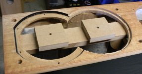
After 2 weeks of cutting out the various peices and then making holes, we hit a snag this morning when somehow my father thought the tweeters we're going to be where the terminal cups are going. Nonetheless, we worked around it and now everything fits and although it's quite a painful process I've loved every second of it.
I've decided I'd like a glossy white finish on them and my dad has primer, paint and finish left over from a job he did on the house not to long ago. Awesomely convenient.
I put the first coat of primer on the wood today and hope to get a final layer on one afternoon this week, so I can paint and finish the wood next weekend. We decided not to rebate the tweeters as we did not plan nor cut in the correct order, I hope it won't be to detrimental but it's a lesson for the next set. 😉
One thing I want to confirm is the crossover layout, I've drawn it up in paint just wondering if someone can have a look and confirm that it'll work. And if it could be more efficient let me know...
Thanks so much to everyone and I'm so glad more and more people are benefiting out of this thread.
I can't wait to get them done and post some pictures of these badboys!
Attachments
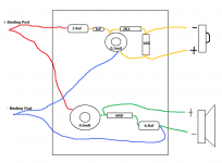
Does not look correct to me.
The capacitor and resistor on the woofer is IF I remember correctly a "Zobel" circuit; part of the driver itself.
So;- the inductor (coil) is in series with the woofer CORRECT!
But the capacitor connects to the positive side of the circuit and goes through the resistor to system ground, that is I usually put the capacitor before the resistor
Also Matt you may have made mistake by not rebating the tweeters; so you may need some felt on the baffle to damp some of those early reflections.
Listen and see how it sounds, then make up your mind.
Most of us need a couple of tries for everything to come together in a build.
Listen and see how it sounds, then make up your mind.
Most of us need a couple of tries for everything to come together in a build.
Alright moondog, I don't exactly understand what you mean if you have any spare time (no hurry) could you draw up a correct version?
As for rebating I'll talk to dad, I think I'll go without the rebate and see how it sounds then if I'm not happy I'll think of a way to get it down.
As for rebating I'll talk to dad, I think I'll go without the rebate and see how it sounds then if I'm not happy I'll think of a way to get it down.
Attachments

Matt, it is as the little bit-map you attached, except that I usually put the capacitor first and the resistor second, I may be totally wrong too as that sketch was given to you by Ralph wasn't it?
I usually attach the Zobel directly to the back plate of the driver, usually with a dab of silicon; just because I find it easier that way
I usually attach the Zobel directly to the back plate of the driver, usually with a dab of silicon; just because I find it easier that way
Hi Matt,
Your in luck. I had a pair of bookshelf speakers that used that tweeter, I tried it without the rebate (don't do it!).
I can show you exactly what happens if you don't rebate the 27TFFC.
http://pix.minirig.org.au/main.php?g2_itemId=1330
In the first plot look at the dip between 6-10khz. That is without rebating. In the second plot the tweeter is rebated.
col.
You may be able to do this free-hand, I have.
Use as big a router bit as you can and take it slowly, make sure the light is good and that the scribed pencil mark is easy to see.
If the rebate is too big you can fill it with bog or putty
Use as big a router bit as you can and take it slowly, make sure the light is good and that the scribed pencil mark is easy to see.
If the rebate is too big you can fill it with bog or putty
Theres an easier way of doing it if the hole is already cut. You can put a piece of rectangular MDF through the tweeter hole and then fix it with screws through the baffle. Drill a hole in it's center to act as the pivot point for your router cut. After, remove the bit of wood and fill the screw holes with a filler. I use car body filler with MDF, dries rock hard.
col.
col.
One thing I want to confirm is the crossover layout, I've drawn it up in paint just wondering if someone can have a look and confirm that it'll work. And if it could be more efficient let me know...
Your crossover layout is fine and the zobel can be connected either way.... RC or CR.... makes no difference.... different builders do it different ways. I don't know what the 1uF cap is doing there as the series cap is specified at 4uF and 3.9uF is close enough. If it's a 0.1uF cap to make up the value then run it in parallel to the 3.9uF so it adds up to 4uF.
Rebating the tweeter is a good idea and is beneficial but don't lose any sleep if you can't do it. Go to a craft shop and pick up some felt that you can glue on around the tweeter or you can use a trick that Bob Brines uses. He adds a trim panel to the baffle which has cutouts for the drivers and acts like rebating.... clever hey. You can do it with a jigsaw using MDF or ply the same thickness (or a tad more) as the tweeter flange.
Look at para 13 and the pics.
http://www.geocities.com/rbrines1/Pages/PP_Construction.html
Another example.
http://www.geocities.com/rbrines1/images/Proposals/Ron_Hanzely_1.jpg
yeah, thats the go!
edit: another trick Iv'e used is to glue a layer of neoprene (wet suit material) which comes in various thicknesses and then paint it satin black afterwards. Looks awesome and gives you a good round over on the edges. Also, adds a very 'dead' feel to the box.
col.
edit: another trick Iv'e used is to glue a layer of neoprene (wet suit material) which comes in various thicknesses and then paint it satin black afterwards. Looks awesome and gives you a good round over on the edges. Also, adds a very 'dead' feel to the box.
col.
Last edited:
just an update,
I have bought the speakers and found somewhere to get the wood supplied, I will preferably borrow or maybe buy a drill and router.
How do you accurately cut circles with a router.
Will I benefit from doubling the critical section of the baffle as in Rabbits design for another speaker that he posted in this thread?
vovo
One thing I want to confirm is the crossover layout, I've drawn it up in paint just wondering if someone can have a look and confirm that it'll work. And if it could be more efficient let me know...
Thanks so much to everyone and I'm so glad more and more people are benefiting out of this thread.
I can't wait to get them done and post some pictures of these badboys!
Rabbitz has already mentioned this, but this WON'T work as is.
Your two capacitors on the tweeter have an effective value of about 0.8 µF, not 4 µF! If you want to add capacitors together, connect them in parallel. But 3.9 µF is close enough and probably within the tolerance of the capacitors anyway.
The order of the capacitor/resistor on the Zobel doesn't matter at all, though.
- Status
- Not open for further replies.
- Home
- Loudspeakers
- Multi-Way
- Kit in Australia