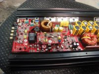
I don't know what the normal current draw is for this amp but 5-6 amps seems a bit high. Power it up and let it idle for ~15 minutes. Does anything (any area of the heatsink, inductors...) get hot?
This is higher than it should be.The idle current is 3-3.5A.Remove the small class D control board(with the amp off ofcourse) ,turn it on and measure again.
Also how do you measure the current?
Also how do you measure the current?
Did the heatsink remain cool?
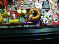
Does that inductor get too hot to hold your hand on continuously in 5 minutes?
Does that inductor get too hot to hold your hand on continuously in 5 minutes?
The heatsink remained cool, After 5 mins the inductor started getting hotter and hotter so i shut the amp down
Do the windings on the inductor appear to have overheated?
Does the board under the inductor appear to have overheated?
Does the board under the inductor appear to have overheated?
windings dont appear that they were overheated. THe board under the inductor apperars to have got warm at some point and is discolored
There's a good chance that the inductor core has been damaged. See if you can get one from carampsguru. If he can't supply an inductor, try to find the value of the inductor.
Ok i left it on a few more mins to see if it would get any hotter. Now the amp goes into protection mode. If the class d board is in the amp. If i take the class d board out amp will power up fine but still current draw of 6 amps.
So now i have to trouble shoot that
So now i have to trouble shoot that
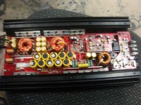
Does the heatsink under the power supply FETs begin to get warm after ~5 minutes?
Did you get your scope?
Did you get your scope?
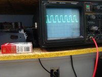
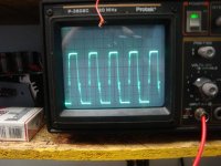
Post the gate waveform from 2 of the power supply FETs (one from each bank). Set the timebase so that ~3-4 pulses are displayed. Set the vertical amplifier to 5v/div.
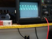
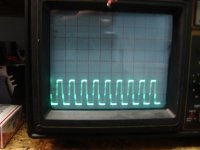
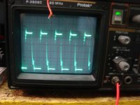
It doesn't look like the gates are being turned off quickly enough. Try it again but, with no input to the scope, set the position of the trace precisely on the bottom graticule line on the scope display. Set the time base one click more clockwise and set the vertical amplifier to 2v/div. Post the photo of the same point you probed on the left photo.
What PNP driver transistors did you use?
What PNP driver transistors did you use?
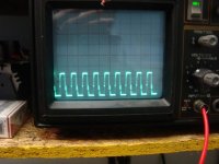
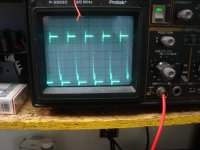
The resolution isn't quite good enough. Set the center knob of the vertical amp fully clockwise and set the timebase 1 more click clockwise. The waveform should extend up ~2 divisions above the center reference line when the vertical amp is set correctly.
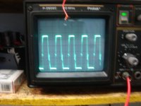
That glitch on the right (falling) edge of the waveform is a problem. There isn't enough deadtime. Post photos of the waveforms on the emitter and base of one of the PNP driver transistors.
- Status
- Not open for further replies.
- Home
- General Interest
- Car Audio
- kicker 1500.1