What's the size of the speaker cutout in the baffle?
I'm using a B&C 18SW115 so it's 422mm.
Rowan
I'm using a B&C 18SW115 so it's 422mm.
Rowan
See this thread: - http://www.diyaudio.com/forums/subwoofers/275969-when-things-dont-go-quite-planned-2.html
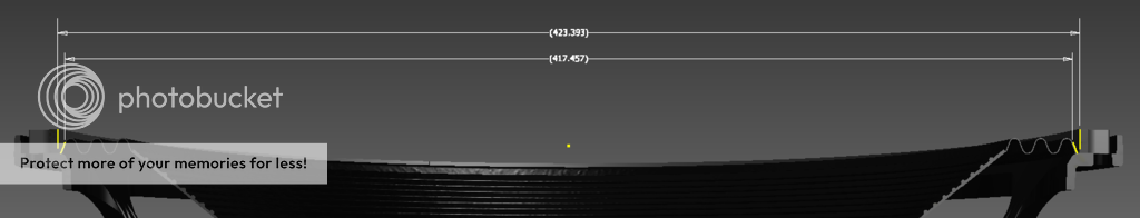
The 422mm spec given by B&C is for when the driver is being mounted through the baffle.
When the driver is being mounted facing into the baffle, you can safely go with a smaller diameter cutout, to minimize the possibility of leaks between the driver's basket and the baffle (and correspondingly losing output at the lower end of the passband). I settled for 418mm, but I think even 416mm should be safe.
No worries:
Thanks for that.
The graphic suggests that if you make the cutout 422mm, you've basically got about 0.7mm of "play" before the foam edge is overlapping the cutout. Shouldn't be a problem if the cutout is a perfect circle and the driver is perfectly centered over it and the foam gasket around the front of the driver's basked is also perfectly centered.
You can however account for any minor imperfections in the cutout or mounting or gasket (like my cousin making the cutout with a jig-saw and no guide 🙂) by making the cutout a bit smaller. It will have no impact on the TH's performance.

I did the cut out with a jig saw unguided then checked with the driver in place and it looks fine, I have some Butyl Mastic (Butyl Mastic | Selleys Australia) which I'll use to seal between the foam and the ply, so it should hopefully seal airtight.
Good progress!
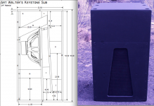
Looks like you doubled up on the "M" brace, which won't hurt, but your placement of the "N/O" braces near the outside of the exit won't be as effective as the original design placement which is visible below.
Art
Attachments
I had a hard time trying to tell where they went. I missed the front on view which would have saved a lot of time and thinking "this seems pointless" I will move them. So basically O just goes on the end so you have something to put the T bolts in? Not in the L shape I made.
The L shape is correct, the T-nuts are mounted on "O", it just should be closer to the exit to brace the lower front panel sections.So basically O just goes on the end so you have something to put the T bolts in? Not in the L shape I made.
I planned on using bondo intead of wood filler becuase I feel it will...wait for it...bond better. Any reason to use wood filler over bondo? I also was unable to get silicon everywhere I wanted (plenty of places i didn't though, one handed messes) Hopefully the PL has everything sealed well there.
Bondo is more impervious to moisture than the wood filler I use, Durham's Rock Hard Water Putty. Haven't had problems with either from a bonding standpoint, but have had problems with Durham's "dimpling" over screw heads when a layer of water stays on the cabinet for a while (days).I planned on using bondo intead of wood filler becuase I feel it will...wait for it...bond better. Any reason to use wood filler over bondo?
Other than the stink and expense, my preference is Bondo.
I'm cutting out the keystone mouth now. I'm going to see if just moving O to the other side of N will still be enough to not compromise bracing. Moving N will be a small project in itself.
Wasn't thinking all the way when I posted that. What I was meaning to say is the braces take up minimal volume so I would just add the two to the sides of the mouth that bolt to the front cover without removing the existing ones.
So to assist in sealing the mouth piece, do you suggest a band of neoprene or other thin foam. Or even running a bead of silicon and flattening it, but leaving enough to be crushed/seal when the panel is tightened?
Using the screw pattern visible in post 628 there was no leakage on the cabinets I built. Thin weatherstrip would be fine if you left enough recess to allow for it's depth.So to assist in sealing the mouth piece, do you suggest a band of neoprene or other thin foam. Or even running a bead of silicon and flattening it, but leaving enough to be crushed/seal when the panel is tightened?
I saw a rather extensive test on the iNuke 6000 amp(and remember Art commenting on it in this thread), and with 33% Duty cycle testing at 4 ohms the author claims it would safely pull out 1800 watt continuous at 31 hz for sub duty without popping either the internal breaker or the external fuse as far as I understood, if run on a beefy fuse.
Would it be sufficient to give two 18tbw100-8 loaded keystones a run for the money per side of the iNuke, giving each cab approx 900 watt each? Could end up a cheap solution reaching around 140 dB capability.
Or would it be safer to use 4 ohm drivers and one a side
Link to the test: http://forum.speakerplans.com/behringer-inuke-nu6000-vs-kam-kxd7200-bench-tested_topic69202.html
Last edited:
- Home
- Loudspeakers
- Subwoofers
- Keystone Sub Using 18, 15, & 12 Inch Speakers