Reverse Engineering Finished
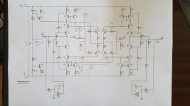
I finally finished the reverse engineering.
There are component differences between the original and the Chinese copy.
Extra components I've designated as 40+.
Components marked SD are for supply decoupling and aren't shown on the schematic.
I still can't see why the op-amps run so warm.
I finally finished the reverse engineering.
There are component differences between the original and the Chinese copy.
Extra components I've designated as 40+.
Components marked SD are for supply decoupling and aren't shown on the schematic.
I still can't see why the op-amps run so warm.
Attachments
I'm using OP27 op-amps from a reputable supplier (RS as it happens).
I've got VCC at +/- 18V, it should be +/- 20V.
The op-amps aren't HOT but are at about 45C which seems warm to me.
The OP27 is rated at +/- 22VDC so that shouldn't be the issue.
I've got VCC at +/- 18V, it should be +/- 20V.
The op-amps aren't HOT but are at about 45C which seems warm to me.
The OP27 is rated at +/- 22VDC so that shouldn't be the issue.
Max power is when opamp output is + or - 20V, with a load of 10k is 2mA (assumed node between R7-R8 stays 0V), so power dissipated is 2*20V * 2mA = 800mW.
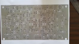
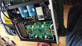
The picture in #49 does not show the OP27's, but if it's 8-Lead PDIP the temp specs are (θJA=103,) θJC=43 °C/W yielding in 0.8 * 43 = 34.4 above room temperature, so it's 45 - 34.4 = 10.6°C in your shed if it was possible to use them as coolers.
Expecting some 20°C instead, there is 25°C temp raise, and with this 43°C/W results in 580mW dissipation, which results in 580mW / (2*18V) = 1.6mA current from the output, lifting the output voltage up or down towards the rails, say some 1.6m*10k = 16V.
So, what is the actual output voltage of the opamps?
Do you think it might be worth adding some IC heatsinks ?
TJC may not remove that much heat.
They are only very warm, not toasting hot.
TJC may not remove that much heat.
They are only very warm, not toasting hot.
If they're already 45°C case temp, the junctions are substantial more hot. HS's are recommended, ICK20L for i.
I did read that these boards do run hot but the only heat I can detect is from the op-amps.
The transistors all run cool.
The transistors all run cool.
I've got some IC heatsinks on order. I'm not quite sure how I'm going to fit them in order to get a decent TJC.
Hopefully they will come with self adhesive pads.
9x9x12mm Heatsink Heat Sink A4988 DRV8825 Ramps Cooling Pi IC | eBay
Hopefully they will come with self adhesive pads.
9x9x12mm Heatsink Heat Sink A4988 DRV8825 Ramps Cooling Pi IC | eBay
Last edited:
SAP's are not great in transferring heat, so a piece of copper wire (1mm?) around the combo, in the length of course, tightened up, will suffice.

Just to re-iterate, this is schematic for the V2.1 boards that are being sold on E-Bay as per #001.
Beware there is an error on these boards as discussed in this thread. It is easily corrected but does stop the board from working.
Beware there is an error on these boards as discussed in this thread. It is easily corrected but does stop the board from working.
Haha, I've found one problem that would certainly stop the boards from working.
I've installed OP275 op-amps instead of OP27.
That would also explain why they were getting rather warm.
I've installed OP275 op-amps instead of OP27.
That would also explain why they were getting rather warm.
All working now.
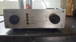
Thank you everyone for your help and comments in this thread, the Kevin Gilmore UnBalanced to Balanced Convertor is now working.
Although the wrong op-amps wouldn't have helped the problem they were not the true source of the problem.
I decided to swap out all the LEDs with "Identical" items, ie all from the same batch.
With identical LEDs throughout the circuit it balances out nicely. The op-amps only help to zero the output to an almost perfect 0mV DC offset.
Kind regards
K&D
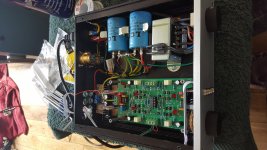
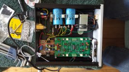
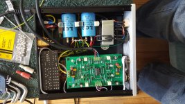
You will notice that I bought a standard LM317/LM337 regulator board but I'm running it from DC rather than from AC.
On first test the 220R resistor on the LM337 smoked. I've got no idea why. I replaced the resistor and the LM337 and it's been fine since.
I wonder if the LM337 was a fake ?
I wonder if the LM337 was a fake ?
- Home
- Amplifiers
- Solid State
- Kevin Gilmore