I think this might be what you need? The Multi Amp aka Dynalo Mk2 - Page 51 - Do It Yourself - www.Head-Case.org
AHA !! It turns out that I was correct. There is a fault on the board. The 10K needs to be connected to the B not the E.
That was what I considered as the only way of making sense of it.The 10K needs to be connected to the B not the E.
Now, if the router made this mistake, or had another bjt in mind, and this other part in mind during routing, be aware that it is possible more errors can be encountered on the board.
Can you post the circuit drawing here so others who feel tempted can cross-check too?
I've still not fully reverse engineered it but according to the posts above the remainder of the board is correct.
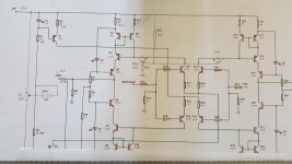
The circuit resembles #24, but with some differences.
The four bjt's in the that340 have cascodes added in their collectors, held at halfway the supplies with two 10k resistors at each supply.
Added in the outputs are extra 49.9Ω resistors, input resistors are 100k.
Integrator input resistors are 100k (at pin 2), current determining resistors R3 and R4 in the current sources for the differentials are 100Ω, so the diff's run higher current.
Obvious some caps on the rails.
And the found error on the board, I could not find others.
Thanks MarsBravo. I lost the reverse engineering around the THAT340, the biasing of the transistors just became so different to the schematics.
The wife's been tidying up and the packets with the op-amps and 49.9R resistors have probably cone up the vacuum cleaner.
Other than that, I'm ready to go.
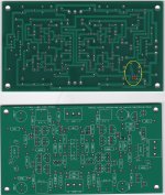
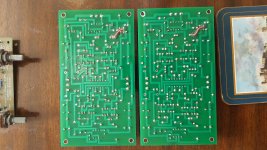
You can see the mod to the incorrect artwork on the bottom of the boards.
Other than that, I'm ready to go.
You can see the mod to the incorrect artwork on the bottom of the boards.
Attachments
Last edited:
I think I've spotted you and the wife with her 'cone-up-the-vacuum-cleaner'!...cone up the vacuum cleaner...
But correct me if I'm wrong.
Oh, I forgot to mention the pot and 15k to the centertap of the two 10k's in the current sources for nulling on your board.
I've decoded the purple board in #8 this morning. It's an elaborate circuit and only the second and end stages are corresponding with #7. The front is the That with same current sources. Two dc integrators to stabilize the circuit and yet four pots needed to tame the thing... why so complex?
Attachments

I spotted that the PCB artwork was incorrect just by reverse engineering the board.
Some guys built the board and found that they couldn't adjust the DC offset.
Between those pieces of information I deduced that the VR should adjust the DC output and that there was an error on the PCB artwork.
Thank you everyone for your help. I will let you know if they work when the missing components arrive.
I think they might 😉I will let you know if they work when the missing components arrive.
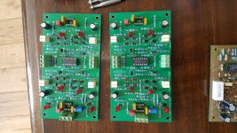
Hmmm, one of the boards works perfectly the other one has a massive offset.
This might be down to my using odds and sods of LEDs.
I'm just finishing off my reverse engineering so that I have a schematic to work to.
This might be down to my using odds and sods of LEDs.
I'm just finishing off my reverse engineering so that I have a schematic to work to.
On both boards the op-amps are running extremely warm, is this to be expected ?
I've reduced the rails to +/-18V as I investigate.
The current draw from the PSU is a reasonable 110mA per rail per channel.
I've reduced the rails to +/-18V as I investigate.
The current draw from the PSU is a reasonable 110mA per rail per channel.
No, not to be expected. +/-18V is near limits of most opamps (40V total), so maybe separate rails needed... not nice on those boards. Was this circuit ready for +/-20V up actually?On both boards the op-amps are running extremely warm, is this to be expected?
Current through from the current sources to the input differentials is depending on the forward voltage over the leds. If they differ, the cs- currents differ too. Better have them somewhat selected.
I'll have a look on your reveng-circuit drawing when/if posted.
I'm wondering if they only did it to get around copyright ?
Might it be worth just adjusting the board to follow the original schematic ?
Might it be worth just adjusting the board to follow the original schematic ?
Same on bottom indeed. The cascodes are halfway the pos or neg rails with two 10k resistors (not only one to gnd).I've only done the top half of the schematic but I'm expecting the same on the bottom.
Check the datasheet of the opamps used: Absolute max ratings Vcc-Vss.The rail voltage in my example should be +/- 20V.
- Home
- Amplifiers
- Solid State
- Kevin Gilmore