yes input is shorted and problem only occurs with two of the outputs (2sa/2sc) installed- whereas with Q31/Q32 installed the bulb stays off and relays click.
You need to look super carefully at what is across the 33 ohm resistors while it is in the above state. As mentioned earlier you will have to look carefully at the signal on each end of the resistor. 100Mhz scope is perfect. I would use both scope channels, DC coupled and calibrated so that each trace overlays the other perfectly when both probes are on the same point. Then measure to each end of the resistor and see if there is any signal of any kind across the resistor.
Thanks @Mooly -
I assume this means with Q31/Q32 installed and no outputs installed?You need to look super carefully at what is across the 33 ohm resistors while it is in the above state
Yes.
We need to to see exactly what is turning the outputs on, whether it is DC or some weird AC instability. If the frequency of any oscillation is high enough it causes 'cross conduction' in the transistors (between each upper NPN and lower PNP) as they are unable to turn off quickly enough. When that happens both are conducting for a short while and that can show as high current flow.
We need to to see exactly what is turning the outputs on, whether it is DC or some weird AC instability. If the frequency of any oscillation is high enough it causes 'cross conduction' in the transistors (between each upper NPN and lower PNP) as they are unable to turn off quickly enough. When that happens both are conducting for a short while and that can show as high current flow.

So back after a couple of days of very much more productive and successful audio work.
When I measure across the 33 Ohm R65/R62 I get -0.27v and +0.27v.
I then put the scope across them and yes there is a signal
I measured this with a frequency meter and it is about 210Khz
I looked at output of Q4 and there is a signal there, but not at the input of Q4
I replaced Q39/Q42/Q43 in case they were leaky- there were not
I removed the switch and cleaned it once again, it tests OK - it is set to the off position
I measured Q1/2/3/4 and Q5 and all the voltages match the circuit (allowing for the dim bulb)
I re-seated the sires form the power supply that go to the board marked A/B/C/D/E
I don't think there should be any signal (it is an AC waveform- the AC meter says about 7mv) on the output of Q4- perhaps this is causing the issue on R62/65?
There should be no voltage across the 33 ohm whether DC or AC (with the bias generator shorted).
I'm not sure 'putting the scope across' them is advisable.
If you see this oscillation as measured from ground then there is a problem. The oscillation should show as a signal at the output node. What is the peak to peak amplitude at that point?
I'm not sure 'putting the scope across' them is advisable.
You can't normally connect the scope directly across these resistors because of grounding issues.
If you see this oscillation as measured from ground then there is a problem. The oscillation should show as a signal at the output node. What is the peak to peak amplitude at that point?
Hi
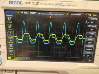
I have attached pictures from the scope with the ground connected to Pin 23 from each end of R62/R65 (they are the same) and TP15,16 and 17 which are also the same as one end of the resistors.
Thanks
I have attached pictures from the scope with the ground connected to Pin 23 from each end of R62/R65 (they are the same) and TP15,16 and 17 which are also the same as one end of the resistors.
Thanks
Attachments
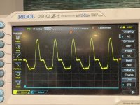
I strongly recommend switching your scope probes to x10 setting. The higher capacitance of x1 probes can provoke oscillation, especially at internal nodes of an amplifier. Switch to x10 and see if there's any change.
Can you just clarify exactly what we are looking at there 🙂 Its not easy without seeing it for real.
Scope grounded
TP15, 16 and 17 are effectively the same point with no output transistors fitted and should all show the same. Is that what we see in the last two images?
The voltage on R62 and 65 needs more info 🙂
You need to carefully look and see if whatever is on those resistors is generating more than around 0.6 volts across the resistors. If it is then it will turn the outputs on and draw current.
Using both scope channels and with both calibrated and set to overlay each other look at the voltage on each end of the resistor simultaneously. If both channels perfectly overlay each other then the outputs can not turn on. If they are separated by at least 0.6 volts then the outputs will conduct.
Even if the DC offset is not zero they should still overlay. If both were sat at +10 or -10 the outputs are still off. It is the difference between the two that matters.
thanks and appreciate remote diagnosis is difficult
for my understanding
1) Scope input is set to ground? (rather than AC/DC)
2) are both channels across the same resistor or one channel per resistor?
Peter
for my understanding
1) Scope input is set to ground? (rather than AC/DC)
2) are both channels across the same resistor or one channel per resistor?
Peter
Last edited:
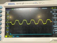
So one probe at each end of resistor, both traces aligned on top of each other, with DC/Gnd/AC coupling all grounded at TP 23 and probes at 10x
Attachments

Last edited:
I think you're getting there 🙂
Without measuring anything yet you first set both scope channels to the same v/div setting and you set coupling to DC initially.
Now set the trace of both on the scope screen centre line.
As a test you can now measure the scopes own CAL waveform. Both traces should overlay perfectly.
Once you are happy with that you connect channel 1 of the scope to the output line which is the junction of the 33 ohm resistors. As a further test connecting channel 2 to the same point should again give two perfectly overlaid traces. If the oscillation is present then the traces should still overlay at this point as they are on the same node.
If that is OK you now connect the second channel to the other end of R62. If the traces are now 'different' you have to look at the voltage difference between the two. If the second trace goes more than about 0.6v higher than channel 1 then that is going to turn the next transistor on.
Moving channel 2 to R65 works the same way but now the difference must ne negative to turn on the PNP transistor. So if channel 2 shows more than negative 0.6 volts it will be turning on the PNP output.
This is just a simulation but it shows what happens. The amp is biased correctly and there is no load. The green trace is the output node, the red trace the other end of R621 and the blue trace is the other end of R629
This is biased correctly remember. The input is 1kHz. The two other traces are separated from the output node by that magic 0.6 volts. It is 0.6 volts because the bias is set correctly at this point.


Now with the bias generator shorted. All points are now very similar in voltage and no current flows in the output stage. The three traces are still all present but almost perfectly overlaid.

So in your image it is the voltage difference between the two that is important. If this exceeds that 0.6v then transistors start to turn on. If the frequency is very high then the transistor conduction begins to overlap because they can not turn off quickly enough and that can cause a current to flow in both. Few a few tens of kHz that shouldn't happen but beyond that it will become an issue.

Without measuring anything yet you first set both scope channels to the same v/div setting and you set coupling to DC initially.
Now set the trace of both on the scope screen centre line.
As a test you can now measure the scopes own CAL waveform. Both traces should overlay perfectly.
Once you are happy with that you connect channel 1 of the scope to the output line which is the junction of the 33 ohm resistors. As a further test connecting channel 2 to the same point should again give two perfectly overlaid traces. If the oscillation is present then the traces should still overlay at this point as they are on the same node.
If that is OK you now connect the second channel to the other end of R62. If the traces are now 'different' you have to look at the voltage difference between the two. If the second trace goes more than about 0.6v higher than channel 1 then that is going to turn the next transistor on.
Moving channel 2 to R65 works the same way but now the difference must ne negative to turn on the PNP transistor. So if channel 2 shows more than negative 0.6 volts it will be turning on the PNP output.
This is just a simulation but it shows what happens. The amp is biased correctly and there is no load. The green trace is the output node, the red trace the other end of R621 and the blue trace is the other end of R629
This is biased correctly remember. The input is 1kHz. The two other traces are separated from the output node by that magic 0.6 volts. It is 0.6 volts because the bias is set correctly at this point.
Now with the bias generator shorted. All points are now very similar in voltage and no current flows in the output stage. The three traces are still all present but almost perfectly overlaid.
So in your image it is the voltage difference between the two that is important. If this exceeds that 0.6v then transistors start to turn on. If the frequency is very high then the transistor conduction begins to overlap because they can not turn off quickly enough and that can cause a current to flow in both. Few a few tens of kHz that shouldn't happen but beyond that it will become an issue.
There is not enough description to me, is the scope picture taken with some input signal, or something else is going on.So one probe at each end of resistor, both traces aligned on top of each other, with DC/Gnd/AC coupling all grounded at TP 23 and probes at 10x
Next pictures should be taken with visible scope settings like Mooly said, voltage per division (volts/div)-vertical units, time division-horizontal units or time with ms, us or ns (seconds). I think that your scope have this details on the screen, but they should be selected to be shown.
After that I will have something to say...
Sorry
Maybe, but I don't know the meaning of 2us, maybe it is horizontal scale, maybe is hold of the signal taken...
It would be nice to write down some details, input signal is not determined (is it still grounded). Every manufacturer have some custom details of the settings, I don't know Rigol, it is similar to my GW Instek, but...
In your situation I would test whole input without output stage and determine that there is no oscillation, take every step to remove this kind of operation, check every trace of the circuit board, maybe something is broken and you don't have good connection (you said that you changed some ELCOs), during this operation breaking some part of the trace is possible.
@Mooly
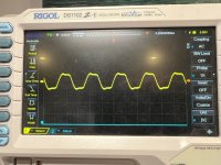
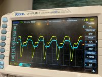
So following your instructions ( I think)
I calibrated the scope.
Tested both channels at the join of R62/R65 and they overlaid perfectly
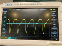
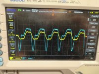
Then checked across R65/R62- the first image is R65 and the second R62
If I am interpreting them correctly there is about 0.25v across each of the resistors
Thanks again, especially for the explanation
Peter
So following your instructions ( I think)
I calibrated the scope.
Tested both channels at the join of R62/R65 and they overlaid perfectly
Then checked across R65/R62- the first image is R65 and the second R62
If I am interpreting them correctly there is about 0.25v across each of the resistors
Thanks again, especially for the explanation
Peter
Attachments
- Home
- Amplifiers
- Solid State
- Kenwood L08M circuit discrepency