I wouldn't expect that capacitor to increase the DC offset.
What's the resistance from the negative speaker terminal to pin 3 of IC6?
What's the resistance from the negative speaker terminal to pin 3 of IC6?
What's the DC voltage measured across that capacitor?
What's the DC voltage from IC6, pin 3 to IC7. pin 6?
What's the DC voltage from IC6, pin 3 to IC6. pin 5?
What's the DC voltage from IC6, pin 3 to IC7. pin 6?
What's the DC voltage from IC6, pin 3 to IC6. pin 5?
With the .1uf film cap installed, or removed and the IC6 pin3 to IC7 pin5 jumper in place there's 26v across C134, IC6 pin 3 to IC7 pin6 is 112mv and to IC6 pin5 is 6.2mv.
Removing the pin3 jumper changes IC6 pin5 voltage to 3.3mv and 530mv across C134, while ICU pin6 remains unchanged. The .1uf film cap makes no difference.
Once the inductor is installed, the amp will not remain on if the .1uf capacitor is installed or if the IC6 pine jumper is in place, or both.
Removing the pin3 jumper changes IC6 pin5 voltage to 3.3mv and 530mv across C134, while ICU pin6 remains unchanged. The .1uf film cap makes no difference.
Once the inductor is installed, the amp will not remain on if the .1uf capacitor is installed or if the IC6 pine jumper is in place, or both.
Last edited:
You can leave the jumper off.
If possible, list the voltages like (include meter reference point):
ICxx
PIN x:
ICxx
PIN x:
You can make notes in-between, where necessary.
Have you been using pin 3 for the meter reference for all meter readings?
If possible, list the voltages like (include meter reference point):
ICxx
PIN x:
ICxx
PIN x:
You can make notes in-between, where necessary.
Have you been using pin 3 for the meter reference for all meter readings?
There may be a difference in the voltage (which needs to be precise) using pin 3 or something farther away.
Please repost the voltages listed below (IC6 pin3 to IC7 pin5 jumper removed), pin 3 as the reference. Post the entire meter display (3 numbers to the right of the decimal). Either copy/paste the text below and enter the values or post as suggested in #87.
What's the DC voltage measured across that capacitor?
What's the DC voltage from IC6, pin 3 to IC7. pin 6?
What's the DC voltage from IC6, pin 3 to IC6. pin 5?
What's the DC voltage from IC6, pin 3 to IC6. pin 7?
These are the readings asked for when the amp is powered up:
What's the DC voltage measured across that capacitor? 533mv across C134
What's the DC voltage from IC6, pin 3 to IC7. pin 6? 115mv
What's the DC voltage from IC6, pin 3 to IC6. pin 5? 2.9mv
What's the DC voltage from IC6, pin 3 to IC6. pin 7? -5.1v
There is a problem that this amp was giving when I first got it and it is doing it right now. I sometimes have to turn it off and back on 2-3 times for it to remain on. Sometimes when remote power is applied, the red LED lights up and then flickers and goes out after a second or two and I have to turn off remote power 2 or 3 times for it to remain on. Also, it hasn't been powered up for two days and it is now powering up with a solid square wave on the outputs/inductor input.
Attachments
Is the inductor in the circuit?
If not, does the amp power up more readily if a load is connected across the speaker terminals?
I wasn't specific enough on the cap measurement. The readings may have changed and the values are critical so I need them again. This may be a better format. Copy and paste the list.
Pin 3 of IC6 is the reference.
IC6:
Pin 1:
Pin 5:
Pin 6:
Pin 7:
IC7:
Pin 5:
Pin 6:
Pin 7:
Connecting a speaker to the output terminals does seem to allow the amp to power up consistently.Pin 3 of IC6 is the reference.
IC6:
Pin 1: -980.0mv descending
Pin 5: 3.1mv
Pin 6: 19.2mv
Pin 7: -5.160(sometimes reads -5.9v/-6v at one time, sometimes the amp shuts down when the probe touches the leg/trace)
IC7:
Pin 5: -2.537v
Pin 6: 115.0mv
Pin 7: -3.937v (drops to -3.5v when a speaker is connected)
With the speaker connected sometimes there is a squealing noise audible. The noise is present when IC6 pin7 is reading -5.9-6v but probing the leg/trace or touching with my finger may cause it to go away and then IC6 pin7 will read -5.2v and there will be no squeal.
The behavior of IC6 pin7 when probed/touched had me wondering whether the solder connection was good so I resoldered the leg and all components in the area of that trace. IC6 leg 7 now reads -5.0 to -5.2v consistently. I think the connection at the junction of C132 was not good. All of the squealing behavior has stopped and the amp no longer shuts off when the ICs are probed.
I would have to reassemble it and test it tomorrow but it still seems that the inductor is getting hot very quickly. Isn't that abnormal?
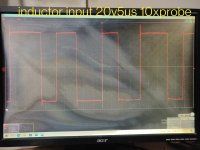
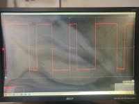
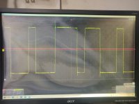
I don't think that's normal. Do you still have an irregular pulse width on the input of the inductor? Every pulse should have the same width.

Is C131 within tolerance?
Also check R157.
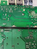
Is the board darkened near the inductor?
Also check R157.
Is the board darkened near the inductor?
Last edited:
C131 reads 48uf
R157 reads 1k ohms
No signs of board burns at the inductor solder joints
Screenshots are of the inductor input with both probes grounded to input GND. The square wave pattern is still irregular.
R157 reads 1k ohms
No signs of board burns at the inductor solder joints
Screenshots are of the inductor input with both probes grounded to input GND. The square wave pattern is still irregular.
Attachments
- Home
- General Interest
- Car Audio
- Kenwood KAC-9104D drawing high current