The solder pads and traces around the center leg of Q304 was damaged and not making proper contact
I don't know if this is causing or will cause a problem but in a class D amp, it can act like an antenna. Go back and repair the connection locally with a short piece of small wire from around the transistor leg, then onto the trace for about 1/4" beyond the break.
Does that change anything?
You stated that you swapped in a known good inductor. Did that inductor come from an identical working amp?
With the 0.1uF cap in place, does the amp still draw excessive current and shut down as it did originally?
Does that change anything?
You stated that you swapped in a known good inductor. Did that inductor come from an identical working amp?
With the 0.1uF cap in place, does the amp still draw excessive current and shut down as it did originally?
Redoing the trace repair did not have any effect on the amps functions.
The inductor was not from the same amp but it read 58uh on my LCR, while the original reads 60uh.
The amp does not function properly with the .1uf capacitor installed, instead there is a once-a-second thump heard through the speaker connected while the red LED dips after each thump so I think the amp is restarting continuously. The only capacitor value that allows the amp to idle quietly is the original 3.3nf. I tried a few close values but they just made the speaker squeal and whine.
Can the amp operate with an irregular square wave like that?
The noise that's getting back to the servo/feedback op-amp is something that I haven't seen. I was trying to get rid of it to see if the pre-inductor waveform would return to normal (what I'd consider normal) to see if that would resolve any of the problems with this amp.
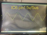
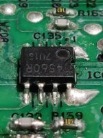
Is IC6 supposed to be a 4560R? IC7 and most of the others that may have been replaced or original in this amp are 4560. Could this IC be damaged? Is there supposed to be a triangle waveform on pin1?
Attachments
From the numbers that you posted, there isn't anything showing that it's defective.
From the service manual:
IC6 (1/2) Triangular wave generation Generates reference signal for digitalizing analog signal
That's the part number shown in the service manual.
From the service manual:
IC6 (1/2) Triangular wave generation Generates reference signal for digitalizing analog signal
That's the part number shown in the service manual.
Just trying to understand why IC6 pin7 has that distorted waveform on it if the only other waveform on the IC is on pin1, and it is a clean triangle. The components connected to pin7 (C132, R158) have no waveform on the other end, or (R159) have the identical waveform but diminished in amplitude on the other end. I am wondering if IC6 is outputting the distorted waveform even though the voltages may be correct. I gather that the noise on ICU pin5 is causing a problem and just wondering if IC6 is to blame.
The noise is residual of the carrier that's coming through the feedback signal at the pre-inductor point.
The noise should be filtered out before it gets to the op-amp but it's not.
You can't see the noise on the inverting input of the op-amp because the op-amp is doing its job, making the inverting input match the non-inverting input.
If you haven't already, download the following service manual from elektrotanya.
KAC-9103 (similar and has some waveforms)
KAC-9104
KAC-9105 (similar and has a nice color diagram on the last page)
- Home
- General Interest
- Car Audio
- Kenwood KAC-9104D drawing high current