It's not good to use the gain control to adjust the input level. Use the level control on the signal source.
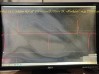
What signal do you see on the input to the output filter inductor? Do you lose that signal when the amp starts to draw current?
What signal do you see on the input to the output filter inductor? Do you lose that signal when the amp starts to draw current?
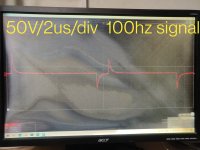
I'm not sure what those are. Does a full rail-rail square wave go to that after the amp shuts down?
The 750mv may be enough to trigger the DC offset protection but it shouldn't draw excess current.
Is the amp out of the heatsink? If so, which FETs start to heat up when the amp starts to draw excess current?
The 750mv may be enough to trigger the DC offset protection but it shouldn't draw excess current.
Is the amp out of the heatsink? If so, which FETs start to heat up when the amp starts to draw excess current?
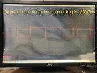
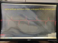
That is what is going into the inductor sometimes. A few times last night and today, I was able to get a square wave going in to the inductor but it is intermittently there. I may be seeing it now and probe again and the clipped waveform is showing. I am attaching pics of both. I had a square wave, put the probe down, unplugged, the RCAs, and when I probed again, the wave was chopped up. It keeps changing randomly. For some reason, I am getting the square wave more consistently now than before.
Attachments
I don't feel any heat from either the PS FETs or from the outputs when the amp is drawing heavy current. The most heated components at that time are the inductor, the rail caps, and the ±15v regulators.
My supply sits at 13.8v unloaded. This amp at idle pulls it down to 11.6v. Turning up the volume on the source unit will pull that supply voltage all the way down under 8v to about 6.8v where my mains limiters are bright and the amp is locked up into current draw mode and will not stop until remote power is shut off. At that point the square wave is gone.
My supply sits at 13.8v unloaded. This amp at idle pulls it down to 11.6v. Turning up the volume on the source unit will pull that supply voltage all the way down under 8v to about 6.8v where my mains limiters are bright and the amp is locked up into current draw mode and will not stop until remote power is shut off. At that point the square wave is gone.
Just turned it off and back on, and the chopped wave is back before the inductor. Made no connection changes, turned it off and back on again, and the square wave is back.
Limiting the supply current to the amp could be causing the problem.
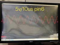
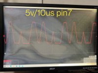
Using the pin 3 of IC6 as the ground, post the waveforms on pins 5, 6 and 7 of IC7.
Using the pin 3 of IC6 as the ground, post the waveforms on pins 5, 6 and 7 of IC7.
I was scared of damaging something with that amount of currently draw. Should I bypass the limiters to perform tests? The following shots are with the probe grounded to pine of IC6 and probing pin5, pin6, and pin7 of IC7.
Attachments
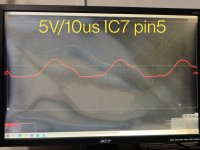
Pin 5 should be quiet.
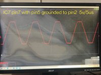
IC7 pin 2 and IC6 pin 3 are both ground. Connect IC7 pin 5 to either of those pins. Does that bring pin 5 to ground (straight line, 0v, no signal present on that pin)?
If so, does pin 7 become a clean square wave?
IC7 pin 2 and IC6 pin 3 are both ground. Connect IC7 pin 5 to either of those pins. Does that bring pin 5 to ground (straight line, 0v, no signal present on that pin)?
If so, does pin 7 become a clean square wave?
That's better. It should get squared up through ICs 8 and 10.
Follow the signal back through the signal chain. Where do you see the signal that was on pin 5 before you grounded it?
Follow the signal back through the signal chain. Where do you see the signal that was on pin 5 before you grounded it?
When IC7 pin5 is grounded to pine the amplifier does not start up and produce rail voltage. It appears that the signal on IC7 pin5 is coming from IC6 pin7 as the same signal is on the other side of a resistor (R159) and capacitor (C131) that connect those two ICs. The ground applied to the ICU side of those components causes the signal on IC6 to not be present, but the amplifier does not power up and produce rail voltage.
IC7 outputs that signal on pin7 when remote is applied even though the amplifier does not fully power up.
As far as I can see, all of the supply voltages for that IC and others comes from the output of the switching supply. Does that waveform remain visible continuously?
No, it doesn't remain after about 5-6 seconds. The rail voltage does start up at ±76v and then the amp shuts down and the voltage dissipates.
Do you see a pulse of DC across the speaker terminals after the remote is applied to the amp? Watch it until the rail voltage drops.
Yes! There appears to be a large pulse of DC (3-9V) a short time after applying remote power at the same time the triangle red Kenwood light goes out.

- Home
- General Interest
- Car Audio
- Kenwood KAC-9104D drawing high current