Qe 33 collector is low because the only current available to it is via the 56k collector load resistor. That resistor is now connected via De15 straight into Re87, the 1.8k.
So we have a series equivalent circuit of 56k + diode and 1k8. So the voltage at the collector will be low... we could even calculate using ohms law and assuming around 0.5 volts dropped across the diode.
Qe34 collector is high because the transistor is fully off. There is no base voltage (and so current) available to turn it on.
The voltage across Ce41 is the big clue and should be around 19 volts according to the diagram. Again we could calculate it. 33 volts AC is about 46 volts peak. 33 volts applied to a 680 ohm and 1.8k in series gives a current of around 13 milliamps. 13 milliamps through 1.8k develops 23 volts... but they say 19 volts. We have to remember that the AC is a half wave quantity and not really the same as 33 volts DC.
The figures are all in the correct ball park 🙂 but you are missing the 19 volts shown and that is derived from a simple series LED and resistor circuit.
#22 reply is very informative and I think I understand what I am seeing.
I guess I’ll examine the wiring to the led. I did remove the front panel once to get to the volume control. Maybe disturbed or shorted led?
I guess I’ll examine the wiring to the led. I did remove the front panel once to get to the volume control. Maybe disturbed or shorted led?
Front panel is off. Continuity good from the leads of the led to their respective pin, 15 and 16. LED lamp is open, I assume blew when I powered up after recapping. There is no sign of shorting to ground, wires are still well insulated.
Just checking in quickly 🙂
That is a bit weird that it should fail like that... actually if the LED were open circuit then you should see a high voltage across it.
It is worth tracing the voltage. Measure from ground to the input side of the LED (pin 16 end). You should have 33 volts AC.
If the LED is open then you will have no voltage on the other end of it, the pin 15 end.
If you have got 33 volts on both sides of the LED then trace the voltage back to the board and to the diode and finally those two resistors.
Bear in mind, the relay is “stuck”. There is no click when powering off or on, and of course, no led light. When I first switched the amp on after recapping, the led came on momentarily, the relay clicked and shut down. It’s been like that ever since.
The relay is likely to be a normally open type, which closes (and clicks) only if all is ok.
So no relay operation will be enabled, since there's a problem.
Last edited:
33vac at the led lead connected to pin 16. Zero vac on the other lead.
I’m going to find a couple of red or green leds and replace this one. If it fails again, then I’ll start searching again.
I’ve learned a lot, thanks to you. I thought led was just a power on indicator, but obviously it is crucial to the operation.
I’m going to find a couple of red or green leds and replace this one. If it fails again, then I’ll start searching again.
I’ve learned a lot, thanks to you. I thought led was just a power on indicator, but obviously it is crucial to the operation.
Hmmm, just trying to carry all this in my head 🙂
Those readings are a possible scenario.
33V on one lead, 0 on the other and yet measuring zero across the LED but that points to something other than the LED. You could only that set of results if the pin 15 end of the lead was open. An open LED would give a high voltage across the terminals of the LED.
(The LED isn't critical but it is an old type which is inefficient and that explains the high LED current I calculated earlier. A modern high brightness one would be blinding at that current)
Also 😉 you can just short the LED out and the circuit should function normally but I don't think the problem is the LED at this point, rather it is either the wiring to it or the diode or resistors or print open circuit.
I just soldered a red led across pins 15 and 16. It lights, the relay clicked and all voltages are per the circuit diagram.
Well that's good 🙂
I'm trying to carry all that was going on in my head, the zero volts across the LED you measured earlier (zero across pins 15 and 16) was/is the confusing one 😉
That's great though excellent result.
I'm trying to carry all that was going on in my head, the zero volts across the LED you measured earlier (zero across pins 15 and 16) was/is the confusing one 😉
That's great though
excellent result.I’ll double check the wiring before I finalize the installation.
I really am very pleased that you were able to educate me and steer me in the right direction.
Donation is in order.
Thank you!
Stay safe
Peter
I really am very pleased that you were able to educate me and steer me in the right direction.
Donation is in order.
Thank you!
Stay safe
Peter
Very interesting thead . AC voltage coming to one end of led is 33 V , but at other end we no longer have AC voltage ,led and diode after it should rectify it. Most multimeters don't measure DC voltages at AC position , maybe because of that it was 0 volts measured across led ,because it was measured as AC ,actually it was DC voltage across open led pins .
Thanks for the kind words Peter 🙂
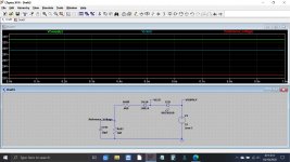
I drew those components out in a simulation so that you can visualise what is happening.
The first diagram shows a simple DC version where the transformer is replaced by a 33 volt DC supply.
There are three key points marked, the supply, the LED voltage and the 'Reference Voltage' which is the 19 volts we needed.
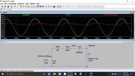
The second diagram shows it all dynamically with an AC voltage source driving it. You can see the 19 volt produced (the red trace) has lots of ripple present... and that is by design and because of the small value of the cap across that supply.
The 19 volt reference serves a secondary purpose here. It allows the relay to drop out near instantly when you switch off rather than relying on the power supply caps to discharge enough to let the relay drop out.
When the mains voltage disappears that 19 volt rail collapses quickly because of the 1k8 resistor across the 10uF cap.
Once the 19 volts has dropped the relay is turned off smartly even though the main reservoir caps are still almost fully charged and the amp still operating normally.
I drew those components out in a simulation so that you can visualise what is happening.
The first diagram shows a simple DC version where the transformer is replaced by a 33 volt DC supply.
There are three key points marked, the supply, the LED voltage and the 'Reference Voltage' which is the 19 volts we needed.
The second diagram shows it all dynamically with an AC voltage source driving it. You can see the 19 volt produced (the red trace) has lots of ripple present... and that is by design and because of the small value of the cap across that supply.
The 19 volt reference serves a secondary purpose here. It allows the relay to drop out near instantly when you switch off rather than relying on the power supply caps to discharge enough to let the relay drop out.
When the mains voltage disappears that 19 volt rail collapses quickly because of the 1k8 resistor across the 10uF cap.
Once the 19 volts has dropped the relay is turned off smartly even though the main reservoir caps are still almost fully charged and the amp still operating normally.
Attachments
With your help I’m learning enough to be dangerous!
Now to tackle the preamp, control board and switch cleaning.
Now to tackle the preamp, control board and switch cleaning.
Pre out, main in mod.
I am really pleased with the performance of the KA7100, and I am considering adding pre out and mains in rca connectors to the rear panel.
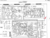
I assume that, from the attached schematic, all that is required, after the connectors are installed, is to connect the output(pins 10 and 8 on the control board) to the respective R and L pre out connector, and the input(pins 1 and 2 on the amplifier board to the R and L mains in connector. All four connectors grounded to chassis(?) or ground points on the control board and amplifier board.
Is it that simple, or am I missing something?
The reason for the mod is to be able to use a minidsp and additional amp.
Merry Christmas to all,
Stay safe,
Peter
I am really pleased with the performance of the KA7100, and I am considering adding pre out and mains in rca connectors to the rear panel.
I assume that, from the attached schematic, all that is required, after the connectors are installed, is to connect the output(pins 10 and 8 on the control board) to the respective R and L pre out connector, and the input(pins 1 and 2 on the amplifier board to the R and L mains in connector. All four connectors grounded to chassis(?) or ground points on the control board and amplifier board.
Is it that simple, or am I missing something?
The reason for the mod is to be able to use a minidsp and additional amp.
Merry Christmas to all,
Stay safe,
Peter
Attachments
Rca grounds should be never connected to chasis ,you must isolate them and use screened cable for inputs and outputs ,maybe one with common screen .
Agree a nice amo, maybe consider changing the speaker posts, the originals are a real PITAI am really pleased with the performance of the KA7100, and I am considering adding pre out and mains in rca connectors to the rear panel.
- Home
- Amplifiers
- Solid State
- Kenwood Ka-7100 troubleshooting help