I'll try the BD139-16, and have a better look at the datasheets from On, Fairchild, ST and Multicomp to see if any seems better in any regard.
Thanks very much for your help !
Thanks very much for your help !
There's both bad news and good news and here it is:BC639/640 from NXP/Phillips are a good bet if you can get them anymore.
BCP53; BCX53; BC53PA 80 V, 1 A
BCP56; BCX56; BC56PA 80 V, 1 A
BCP52; BCX52; BC52PA 60 V, 1 A
BCP55; BCX55; BC55PA 60 V, 1 A
BCP51; BCX51; BC51PA 45 V, 1 A
BCP54; BCX54; BC54PA 45 V, 1 A
BCP69, BC869, BC69PA 20 V, 2 A
BCP68; BC868; BC68PA 20 V, 2 A
The bad news is that the packages are so tiny and the good news is that they are available.
The BCP can be soldered with an ordinary soldering iron, the BCX is impossible and I haven't tried the new flat pack. I just wish they came in TO126 or Dpak sizes.
Last edited:
Thanks again !
I can use the the BUP41 for the 5V 50mA positive rails that supply the DAC ICs. I also have two (L/R) ~15mA +/-15V supplies for the op amps so maybe I'll try all BC327/337 for them and see if they pop, and if they do, ST BD139-16/140-16.
I have another quick question - if I want to set the voltage drop / output using a potential divider, would this work ? My input voltage would be 21V, and output between 12V and 9V, @40mA, R2 and R3 are created using a 10K potentiometer. The 2SA would be a BUP41 with a heatsink. C1 might need to be smaller so the RC delay isn't too long, say 47uF.
Thanks !
I can use the the BUP41 for the 5V 50mA positive rails that supply the DAC ICs. I also have two (L/R) ~15mA +/-15V supplies for the op amps so maybe I'll try all BC327/337 for them and see if they pop, and if they do, ST BD139-16/140-16.
I have another quick question - if I want to set the voltage drop / output using a potential divider, would this work ? My input voltage would be 21V, and output between 12V and 9V, @40mA, R2 and R3 are created using a 10K potentiometer. The 2SA would be a BUP41 with a heatsink. C1 might need to be smaller so the RC delay isn't too long, say 47uF.
An externally hosted image should be here but it was not working when we last tested it.
Thanks !
Last edited:
Hello again,
I just realised it might be far easier and more effective to replace the string of diodes with a 12V zener, so this would drop about 12.7V ? So 21V in and 8.3V out. This would be fine for my application. Would the higher voltage drop cause any issues, except of course the need for a heatsink on Q2 ?
BTW, if you don't like me using your images in this way, please let me know. I just thought it's the easiest way to describe the changes.
I just realised it might be far easier and more effective to replace the string of diodes with a 12V zener, so this would drop about 12.7V ? So 21V in and 8.3V out. This would be fine for my application. Would the higher voltage drop cause any issues, except of course the need for a heatsink on Q2 ?
An externally hosted image should be here but it was not working when we last tested it.
BTW, if you don't like me using your images in this way, please let me know. I just thought it's the easiest way to describe the changes.
N comes before the P means you select the lower numbers before the higher numbers................If BC550C is the NPN part then that's what it should be. I mix them up all the time! Must fix that...
Only works for this series. Other makes country codes are all over the place, except 2sa/c.
So if I understand correctly 240VAC->340VDC. 30mA*220R=6.6V. So I have 13.4V to work with.
Merlin, what do you think about this? The 220R/220u RC is from your supply. It took some determination to make it safe from overvoltage and inrush current, but I like how it turned out.
Don't put more than 330uF between the Kmultiplier and the HV2. Capacitance after the HV2 is okay because it will be limited to 30mA inrush.
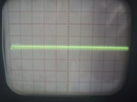
Thanks Keantoken, before to make it I will measure with the scope real ripple between the PSU & SSHV2.
use psud2
Thanks to remember Andrewt, I will measure with the scope.
Hello again,
I just realised it might be far easier and more effective to replace the string of diodes with a 12V zener, so this would drop about 12.7V ? So 21V in and 8.3V out. This would be fine for my application. Would the higher voltage drop cause any issues, except of course the need for a heatsink on Q2 ?
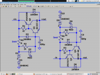
To use that schematic you need to turn the zener upside down and add a 5mA resistor from it's bottom to ground. However this way the Kmultiplier will still track the input voltage. Is this the desired effect? I don't think so, and I would rather replace the upper two diodes with a 5mA resistor, and put the zener below in series with a diode to put the output less than a diode away from 12V.
One of the reasons the Kmultiplier works is because it normally has such low Vce. With 2V Vce the output transistor can handle its max Ic within SOA. However you won't get this benefit if you step a 21V supply down to 12V, so mind the inrush and output dissipation. If the output dissipates more than 2W you'll need a heatsink.
Here is a version of the Kmultiplier for a fixed output voltage. Choose the Zener for whichever output voltage you need and size R5/6 for 5mA of current.
Merlin, I think it is safe to put in the lineamp box. However if you are going to swap power supplies at any point I would put it in the supply box because it needs the 220R/220u RC up front to limit inrush.
Attachments
Last edited:
Kean,
You are so helpful - thank you. I've got it sorted in my head now so thank you very much. I greatly appreciate your help.
In my case, there'll be just under 8V across R5 (20.5V in, - 12.7V for the diode+zener) so 1.6K resistor.
I've ordered parts and I found some ME210/200 too, so I'll let you know when I've tried this out.
I'm also very interested in an smd version so I hope someone will do a pcb ....
Here are Farnell's part codes if anyone needs them :
1084508 BD139-16 STMICROELECTRONICS
1084566 BD140-16 STMICROELECTRONICS
1126461 MJE210G ON SEMICONDUCTOR
1126460 MJE200G ON SEMICONDUCTOR
9556109 1N4004RL ON SEMICONDUCTOR
1228215 BC337-25 FAIRCHILD SEMICONDUCTOR
1853514 BC327-25 FAIRCHILD SEMICONDUCTOR
1782479 1N4148TR FAIRCHILD SEMICONDUCTOR
Last edited:
You can use the 2SC4793/A1837 pair, since you have low current it will work better.
Still Farnell & RS don't have here in Europe.
Can you get BD139/140 from ST? Genuine 2SD669/B649?
Yes BD139/140 from RS, only to be sure BD139 to replace 2SA1930 & BD140 to replace BC337, right?
Can't get 2SD669/B649.
Last edited:
I have have bought 1930/5171 from Mouser
funny, I just now found a Poland supplier
http://www.micros.com.pl/25,about-micros-firma.html
funny, I just now found a Poland supplier
http://www.micros.com.pl/25,about-micros-firma.html
- Home
- Amplifiers
- Power Supplies
- Keantoken's CFP cap multiplier