A jfet current source will improve specs dramatically.
- keantoken
1. The circuit diagram is unreadable.
2. There is no indication what the different colors mean.
3. The JFET current source isn't drawn in the diagram, only general current source is drawn.
The color scheme is no different than the last image. If you can't read it, hover the mouse and you will see a zoom button in the lower left.
Perfect or not, some sort of current source will improve performance. That was the point I intended to make.
- keantoken
Perfect or not, some sort of current source will improve performance. That was the point I intended to make.
- keantoken
The color scheme is no different than the last image. If you can't read it, hover the mouse and you will see a zoom button in the lower left.
Perfect or not, some sort of current source will improve performance. That was the point I intended to make.
- keantoken
There is a possible difference between "some sort of current source" and a detailed, specific current source. Either you are into simulation exercises, or you present a circuit that others can build.
I never told anyone to build that circuit. Be patient if you will, I'm not done!
Firstly, all of these circuits are hardly stable. If you built them in real life, they would go insane. Right now I'm determining how best to stabilize them.
- keantoken
Firstly, all of these circuits are hardly stable. If you built them in real life, they would go insane. Right now I'm determining how best to stabilize them.
- keantoken
Okay, the pictures are crappy. It doesn't matter much, because they're not final either. Sorry to be short, but if you can't read the picture, don't try building it. I'm just trying to spark some helpful conversation.
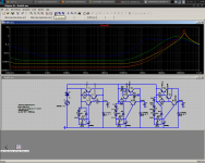
I'm switching gears to the 300mA version again. I was conservative with the original design, but as it turns out, being conservative has bit me in the **** every time. The single best thing you can do to increase performance is to increase the current through the driver transistor. This increases the transistor's transconductance, which the slave's impedance is divided by to produce the final output impedance value. I put the maximum at 20mA, as this is as far as most good small-signal TO92's go that still have good Ft. Decrease to 15mA, considering the Ib of the outputs.
A Jfet should decrease noise, but I don't know much about that. In any case we need a Jfet with low noise and high Idss (20mA max), and tempco is not important.
BTW, my 2SC5171 and A1930 models are VERY broken, I wish I had seen this earlier. I've substituted different models.
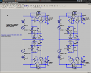
Schematic and Zout plots at 300mA. There is actually little difference between the resistor and Jfet. I think this is because at such low currents, there is little voltage variation across the resistor.
- keantoken
I'm switching gears to the 300mA version again. I was conservative with the original design, but as it turns out, being conservative has bit me in the **** every time. The single best thing you can do to increase performance is to increase the current through the driver transistor. This increases the transistor's transconductance, which the slave's impedance is divided by to produce the final output impedance value. I put the maximum at 20mA, as this is as far as most good small-signal TO92's go that still have good Ft. Decrease to 15mA, considering the Ib of the outputs.
A Jfet should decrease noise, but I don't know much about that. In any case we need a Jfet with low noise and high Idss (20mA max), and tempco is not important.
BTW, my 2SC5171 and A1930 models are VERY broken, I wish I had seen this earlier. I've substituted different models.
Schematic and Zout plots at 300mA. There is actually little difference between the resistor and Jfet. I think this is because at such low currents, there is little voltage variation across the resistor.
- keantoken
Attachments

I believe both versions will work, and I built the resistor version which was stabilized with electrolytic bypass (NOT film, but I want to make it stable with films).
- keantoken
- keantoken
I never told anyone to build that circuit. Be patient if you will, I'm not done!
Firstly, all of these circuits are hardly stable. If you built them in real life, they would go insane. Right now I'm determining how best to stabilize them.
- keantoken
This is a DIY forum. Why wouldn't you publish a schematic only after finishing playing with simulations and actually building one?
This is a DIY forum. Why ....?
Here is a good question: What is your problem?
Strive to answer that and then come back and see if you can make a relevant contribution instead of constantly picking fights.
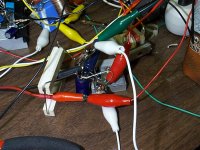
Here Joshua, I built it, and it works EXCEPTIONALLY WELL!
56db input isolation, which was better than last time (tested at about 200mA). Input ripples are 63mV, output are 100uV. Noise is >10uV as far as I can tell.
Josh has a point, but despite that others here don't mind me posting untested schematics just to see what I've been doing as of late. This forum is a casual place, so if you want a scrupulous design team you'd better say so from the beginning, before the mood of the thread is set.
I have to extend great thanks to HiFi as he spent his own money to get me the parts this reg was made from.
So the question is, why were HiFi's results not as good?
- keantoken
Attachments
Also, the circuits in post 146 are not unstable, in case anyone got the wrong idea. I just built the resistor version (still don't have jfets to test), and it is close enough to simulated specs to satisfy me. While the Jfet version hasn't been built, I'll put my money on it.
I used 1000uF for the reference capacitor, and the same for the output capacitor.
- keantoken
I used 1000uF for the reference capacitor, and the same for the output capacitor.
- keantoken
I am wondering if it is convenient, and if so, could you please increase the load current to 300mA and the input ripples to 400mV, which would produce identical conditions to my set up?
On my end I could possibly test on 200mA current with 63mV ripples and see if my figures match yours but I may only be able to find time in the coming weekend.
On my end I could possibly test on 200mA current with 63mV ripples and see if my figures match yours but I may only be able to find time in the coming weekend.
The single best thing you can do to increase performance is to increase the current through the driver transistor. This increases the transistor's transconductance, which the slave's impedance is divided by to produce the final output impedance value. I put the maximum at 20mA, as this is as far as most good small-signal TO92's go that still have good Ft. Decrease to 15mA, considering the Ib of the outputs.
A Jfet should decrease noise, but I don't know much about that. In any case we need a Jfet with low noise and high Idss (20mA max), and tempco is not important. - keantoken
From my measurements the 100R would have 7mA averaged current. Reduce the 100R to 68R gives 10mA. I have many 2SK170 with Idss up to 12mA. The J111 you indicated has Idss 20mA, but individuals can go way over that.
Does anybody know of any jFETs that is most suitable?
The Jfet in simulation doesn't improve input isolation or output impedance. Should improve noise though, no?
- keantoken
- keantoken
A K170 can have 45R equivalent resistance from D to S.
P.S. There are Zo differences in #146, aren't? Especially in the V- charts.
P.S. There are Zo differences in #146, aren't? Especially in the V- charts.
I will find some time tonight to replace the 100R with a jFET 2SK170 and see if there is any subjective improvement. I don't have the time and the right parts to do the 200mA 63V tests though as I need a different raw supply and load from the Marantz.
There are differences, but they are very small.
I'm working up the Vout to 7.5V to get 300mA into 25R load. The circuit's LF performance is good, so it takes some time for the output to settle at it's final value.
- keantoken
I'm working up the Vout to 7.5V to get 300mA into 25R load. The circuit's LF performance is good, so it takes some time for the output to settle at it's final value.
- keantoken
So the question is, why were HiFi's results not as good? - keantoken
I will send you my wiring guide to you when I get home today, you may check if the wiring is correct. Because I have built two boards with identical result, each has both rails, it is not possible to be a cold soldering joint or wrong connection.
It is possible that my measurements are crapy / my oscillioscope is crapy.
In any case, I am very pleased with your result. You have built it and proved it achieving good result very close to simulation. Other builders should use your result, not mind.
Although I got only -3XdB something (in my possibly unreliable measurement, or perhaps it is better), subjectively it has already produced a giant step forward for my Marantz SACD player, now comparable to the very best players IMHO.
- Home
- Amplifiers
- Power Supplies
- Keantoken's CFP cap multiplier