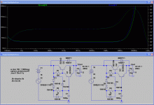
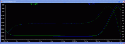
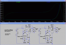
That is not what I read into your previous explanation.
Post 1225 and 1227 clearly show the NPN performing better over the vast bulk of the frequency range.
The latest shows the PNP performing better.
Are we looking at a different type of report on different performance characteristics?
Post 1225 and 1227 clearly show the NPN performing better over the vast bulk of the frequency range.
The latest shows the PNP performing better.
Are we looking at a different type of report on different performance characteristics?
That broken fuse is ominous. If there is a problem, it is likely between the fuse and where the transformer paths combine. What components are between?
- keantoken
- keantoken
The fuse is just at the output of the transformer before going to the rectifiers. The broken fuse was possibly due to the increase of about 30% capacitance of local bypass at the load, from 5,640uF to 8,160uF. Turn-on surge current may be higher. I have now reversed it back to 5,640uF.
I replaced the fuse. The sound is subjectively cleaner. The 3mV ripples are still there. Your simulation of the Marantz reg shows about -70dB (0.00032) ripple rejection. Given it has a 11V rail 3.5mV would be the simulated ripple amount if little filtering is made. I guess it matches your simulation well. I am sure that adding the K-multiplier will reach about -140dB rejection so all ripples will be gone. However, I am not sure if it will make it sound better or worse, as it adds about 0.07R series resistance to raw supply. It is definitely worth trying though. Your K-multiplier's output impedance of about 0.07R is WAY WAY lower than all others I have seen (in tens even hundreds of ohms) but still it is a resistance. We can argue that 0.07R is better than many electrolytic caps, but bear in mind there is a difference - the electrolytic cap is in a shunt position, while a C-multiplier is in series.
I don't know how others have come to their positions that they don't mind some series resistance at the raw supply. Iko's C-multipliers for his measurement preamp is one example, while many choke input supplies are other examples. As I reported previously, I have tried small choke input supplies, LC or RC networks for raw supply. After extensive listening comparisons, in the end, I ditched all the L and R, as I found the treble is cleaner without them. Even 0.1R in series obviously degraded the sound in my power amps. But that was just for me. Your experinece and your ears are different from mine.
Even for the Iko reg, at one stage when I was doing some experiments, I placed the raw supply away from the reg, considering the reg has 3 digit ripple rejection and it should not care about the raw supply. I found the treble was a bit harsh. I tried using LC and RC network in the raw supply without success. In the end, I used C only and put the raw supply right at the input of the Iko reg, especially putting in 6 x 1.1uF MKP right in front of it, the harshness was gone and the treble became silky smooth.
But then your 0.07R may be low enough not to cause any problems. I am planning on replacing the Marantz rectifiers with the ones with higher rating, so that I can retain large capacitance in front of and at the output of the K-Multiplier. This should counteract the effect of the series resistance a bit. I am hoping the reduction of mains ripples will bring in more benefits to off set the disadvantage of increasing the series resistence slightly.
When I looked at the Marants PSU board I got worried, as I have no experience working on it. It has too many connections to everywhere and too many screws. I hope I won't screw it up.
I think I have gone pretty far out of topic and should stop asking questions about my own project and let you guys to continue on discussing the Iko reg.
Regards,
Bill
Just a brief report - I have built Keantoken's K-Multiplier and am using it in my CD player before the Marantz regulator for the audio circuit. I have not got it working 100% yet but it already gives a worthwhile improvement on sound clarity and details.
Here is some preliminary test result of the K-Multiplier (http://www.diyaudio.com/forums/powe...-shunt-voltage-regulator-124.html#post2336298).
It works well on my Marantz SA11S1. I rebuilt it with Rubycon ZL replacing the Panasonic FC, and bypassed the Rubycon ZL with 1u1 MKP. I also replaced the transistors from 2SA1837 to 2SA1930 and from 2SC4793 to 2SC5171, after Keantoken's approval. The new ones are of much higher spec and can work with higher current. On the positive rail, 400mV ripples were reduced to basically a flat line. On the negative rail reduced to a few mV (I need to debug what it is). The simulated ripple rejection was over -60dB, so at least I have proven that it works as simulated on the positive rail.
The Marantz has about -60dB ripple rejection. That is why a pre-reg like the K-Multiplier may be helpful. With -60dB rejection, a 1V ripple is reduced to 1mV, but in line level, noise of 1mV is still significant. An obvious requirement for such a pre-reg is low voltage drop, and the K-Multiplier provides that. I have measured the voltage drop to be around 1.5V to 1.6V, good enough for this particular use. Now combined the pre-reg with the Marantz reg, even with the "faulty" negative rail (-35dB?) a 1V ripple is reduced to a theorectic 20uV, which is really good enough.
Subjectively, the sound is more detailed, fuller, richer, smoother, after my latest round of mods including adding the K-Multiplier as the pre-reg and some others.
I compared my modded Marantz SA11S1 ($3,500? + $200? parts) to an older generation top of the line Wadia DAC ($40,000?) last Sunday, and today compared it to an EMM Labs seperates ($25,000?). Sound wise, those SACD players are excellent, and they used to kill my Marantz instantly. However, as for now, I prefer my Marantz, as its sound is more neatral. On the coming Monday, I am going to compare it to a PlayBack Design MPS-5 ($15,000).
Last edited:
Don't know if the Fairchild models for European classic BJTs are as good as their KS series models but here it is again with BD139-140 BC550C-560C and Panasonic FC 1000uF/63V & 33uF/63V data sheet impedances. For what it may worth.
Attachments
If it's used before the regulator then there's no point in it having low Zout. It better have very good filtering performance. Just my 2c.
But it wouldn't be better Zo than the shunts either so to use it after. Not where many stages with enough signal differences are involved. For local residual power line noise filtering of low signal stages of no PSRR, maybe.
Hi,
none of the components have to dissipate high power, due to the low Vdrop from input to output.
Consider only the output current rating (and hFE at operational current) of the devices relative to your actual current demands.
none of the components have to dissipate high power, due to the low Vdrop from input to output.
Consider only the output current rating (and hFE at operational current) of the devices relative to your actual current demands.
Can it handle 600mA.... My two shunts are running at 300mA each 🙂
You would need something like the 2SA1930 as master transistor so to meet the hFE requirements that Andrew mentioned for 600mA.
I designed the circuit around what was needed or wanted at the time, which were in order of desire:
low voltage drop
good input isolation
low Zout
The main concern was to be careful not to upset proceeding circuitry. This needed a predictable low voltage drop, which I set by relying on diode potentials. For ultimate input isolation something like Iko posted (double or cascoded C-multiplier) would be best.
HiFi decided to adapt the circuit for use in his system and it has/is undergoing refinement. I think Salas' idea to use the BC5x6 transistors is a good one.
For the moment I feel content to think of it as a modern update to the traditional C-multiplier. While the original fulfilled its function well enough in textbooks, the field finds it wanting in output impedance. The most compact solution to me was to use the CFP.
- keantoken
Storm, the 100R resistors could be replaced with Jfets, with some reward but I wanted the circuit to start simple BEFORE getting complex. This way it could be lashed up quickly by less adventurous folks.
I support any refinements, but maybe someone should start a new thread about it.
- keantoken
I support any refinements, but maybe someone should start a new thread about it.
- keantoken
And as Andrew pointed out, the devices dissipate minimal power. This is intentional.
The other reason for D7/D8 (besides quick start-up time), is to that the full startup voltage isn't applied across the output transistor during startup, possibly into a large output capacitor, easily exceeding SOA. The diode limits this, making it possible to use the regulator even at higher voltages then the transistors are rated for. This would seem to be bad policy perhaps, but if the Vce goes above a few V then something is already wrong with the circuit.
- keantoken
You would need something like the 2SA1930 as master transistor so to meet the hFE requirements that Andrew mentioned for 600mA.
If running 300-400mA current, no heatsinks are needed for 2SA1930 / 2SC5171. Hfe is higher when running hotter.
- Home
- Amplifiers
- Power Supplies
- Keantoken's CFP cap multiplier


