It still acts to multiply capacitance, with the same drawbacks in that regard as a normal multiplier. The difference here is that the output voltage has been largely shielded from variations in supply voltage, via filtering (CCS, capacitors, diodes). In this case bass extenstion will be the best, because of the high source impedance (CCS) which will give the capacitor/s a large time constant.
I like your circuit Storm, and using the CFP will improve it's performance quite a bit.
I was right, NPN BJT is better, but CFP is still worse for HF impedance.
- keantoken
I like your circuit Storm, and using the CFP will improve it's performance quite a bit.
I was right, NPN BJT is better, but CFP is still worse for HF impedance.
- keantoken
Attachments

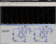
It looks like in StormSonic's circuit the capacitor can be eliminated completely with little impact on performance, except perhaps noise.
- keantoken
- keantoken
post1216 shows a regulator.
It is a follower just like Pass often recommends.
The output voltage = Vbe + LED Vf.
and removing the capacitance proves it is not a capacitance multiplier
It is a follower just like Pass often recommends.
The output voltage = Vbe + LED Vf.
and removing the capacitance proves it is not a capacitance multiplier
It looks like in StormSonic's circuit the capacitor can be eliminated completely
Last edited:
Thanks, guys.
Keantoken,
Could you provide a "final" C-Multiplier schematic including selected transistors that are ready to be built? Some pictures of simulations are welcome. I am happy to be a builder/tester here. The result is a C-Multiplier of your design. Given the circuit won't be complicated so part counts and price are of no issue. It needs to have both rails of around +/-17VAC (after rectification) input, with a voltage drop (2 x 0.65V?). I will put it in front of the Iko reg (+/-29VAC though) for the first test, and if successful, put it in my Marantz CD player before the Marantz reg. I will report how it sounds here.
Regards,
Bill
First thing, you said Marantz used a "very simple" series reg. Can you tell what type it is? Does it use feedback (good impedance), or not (normal BJT impedance)?
In both cases, using a low output impedance prereg may be a waste of effort, because the circuitry will see the Marantz reg's impedance no matter what. Knowing this I will focus on line rejection rather than output impedance.
Can you describe the regulator voltages in more detail? Earlier you stated 15V input voltage.
The 1.3V drop limit is difficult to work with, because bias resistors necessarily add to the Vbe's already present between input and output. Is it okay to go higher than this?
- keantoken
Last edited:
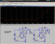
This circuit has the lowest voltage drop and output impedance, with a good PSRR of -54db. If higher voltage drop is allowed, better specs can be achieved. I doubt this is necessary though.
Choices for Q1 in order of order of decreasing preference:
MPSA18
2N5089
2N5210
2N4401
2N2222
BJT's with lower gain may be used, but voltage drop will suffer.
For Q3, choose the highest gain normal PNP transistor you can find. Even so, output drop may be around 300mV worse than the NPN version. Decreasing R4 can fix this, but will change the bass response and I imagine you want the bass response for + and - regs to be equal.
For the power BJT's, anything you would use in an audio amp should work, but if in doubt ask.
- keantoken
Attachments
For C1 and C2, bigger is always better. These will delay turn-on however.
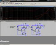
For the power BJT's, the 2SC5200/A1943 seem to work best in simulation. Following are the MJL1302a/0281a. However these are power BJTs, good to 10A or more - what output devices are used for the Marantz reg and their current rating? How about downgrading to 2SA4793/C1837? This improves BW considerably, to over 100KHz for both NPN and PNP, at -64db PSRR.
- keantoken
Last edited:
Here is the output impedance using the 2SC4793/A1837 pair
How about the lowly BD139/BD140(-16). Should be easier to get and have with similar specs?
How about the lowly BD139/BD140(-16). Should be easier to get and have with similar specs?
They should work fine. Phillips datasheet specifies 190MHz/NPN 160MHz/PNP, which is really good. I have been weary of these since for some reason the purveyors don't seem to think that stating the Ft or Cob on the datasheets would be a selling point. Phillips got smart, but even their datasheets don't state Cob.
- keantoken
- keantoken
Keantoken,
Thanks a lot. I am as busy as usual but will send you a private email with a bit more information about the Marantz reg when I have the time in the coming couple of days. My current job is with a government department and they restrict forum access so I can only access the forum at night when the day is done.
Regards,
Bill
The K-Multiplier is born
Okay, here goes...
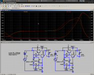
I have been consulting HiFi to create a preregulator that matches his application, and this is what I came up with. It is pretty much a Hi-fi C-multiplier. I call it the K-multiplier.
It will handle any load up to 1A, because the voltage across the outputs is limited to 2.7V - 1A*2.7=2.7W. I would not recommend drawing more than 200mA, since this gets into the outputs' low-beta region and performance will drop.
Voltage drop is about 2V. This can be decreased to about 1.3V if we bypass, say D5. However, a large drop in input will saturate the 2N5xx1 transistors.
This is designed as a prereg, not for high-ripple conditions. It is to improve the performance of later regulators. It will work in high-ripple situations, but you should add diodes to the string D1 and D5 depending on how much ripple you have.
HiFi encouraged me to post this here, and I might as well post the finished design, so someone can spot my errors...
- keantoken
Okay, here goes...
I have been consulting HiFi to create a preregulator that matches his application, and this is what I came up with. It is pretty much a Hi-fi C-multiplier. I call it the K-multiplier.
It will handle any load up to 1A, because the voltage across the outputs is limited to 2.7V - 1A*2.7=2.7W. I would not recommend drawing more than 200mA, since this gets into the outputs' low-beta region and performance will drop.
Voltage drop is about 2V. This can be decreased to about 1.3V if we bypass, say D5. However, a large drop in input will saturate the 2N5xx1 transistors.
This is designed as a prereg, not for high-ripple conditions. It is to improve the performance of later regulators. It will work in high-ripple situations, but you should add diodes to the string D1 and D5 depending on how much ripple you have.
HiFi encouraged me to post this here, and I might as well post the finished design, so someone can spot my errors...
- keantoken
Attachments
Hi keantoken,
Many thanks for all your work and simulations.
I have interrogation about using 1000µF. Since this design is a capacitor multiplier, it will multiply everything coming from this capacitor. It will multiply good effects and bad effects (like coloratura, non linearity...!). Don't you think that using 100µF or 10µF might be more realistic?
Probably, it will be easier to find good 100µF than good 1000µF.
Thanks for all replies...
There won't be any measurable degradation from using a 1000uF cap that I can see.
100uF is totally fine, the bass at audio frequencies will hardly be affected.
- keantoken
100uF is totally fine, the bass at audio frequencies will hardly be affected.
- keantoken
You could not see any coloratura in any simulator 😉There won't be any measurable degradation from using a 1000uF cap that I can see.
This simulation goes to 1GHz. Do you think that 1000µF is able to work at 1GHz?
No, surely not, but I look anyways. You can always bypass that cap with smaller film caps.
The regulator should be decoupled by at least 10uF.
BTW, it is a joke to take credit for this circuit. Nothing special!
- keantoken
The regulator should be decoupled by at least 10uF.
BTW, it is a joke to take credit for this circuit. Nothing special!
- keantoken
reversing that diode seems to make a big phase difference.
Why is the PNP performing better this time over most of the frequency range?
Why is the PNP performing better this time over most of the frequency range?
- Home
- Amplifiers
- Power Supplies
- Keantoken's CFP cap multiplier