I wonder if the transient peak capability of the reverse protection 1n4004 failed?
Then forced the back current through the transistor?
Then forced the back current through the transistor?
Maybe I pulled too much current when testing... I used small high power resistors to simulate 400mA on the psu output but the 15w resistors got really hot... I burned myself... so I must have stretched the kmult too far during testing.
Also I am using 0.25w 47r resistors... maybe a mistake
Also I am using 0.25w 47r resistors... maybe a mistake
I wonder if the transient peak capability of the reverse protection 1n4004 failed?
Then forced the back current through the transistor?
Yes, that might be it also, because I discharged the caps after every test using a small resistor.... that may have produced some voltage peaks.
Hi Kean.... after some time listening to my upgraded headphone amp, using the kmult before the BiB regs, I must confess it is a must. The sound is much more relaxed while retaining all the high freq detail and providing a much more intelligible bass.
A real winner in this case.
Now I am gathering info for my next project: A low cost class B power amp using the schematic from JG Nobrainer. In this amp the input stage is an opamp that should draw only 8mA from the psu.
I know opamps excel when powered with good clean voltage so I was wondering if I could use a kmult there.
Overall amp psu output will be around 35v so in order to feed to opamp I will use a 317 337 series regs to reduce voltage to 18volts and would like to place a kmult after those regs.
As the opamps will draw only 8mA, is there any mod I can do to the kmult to make it work smoothly with such low currents ?
Regards
Ricardo
I recommend getting more than 25mA current any way you can. You might hang a resistor off it to get the necessary current. I could adapt the Kmultiplier for lower currents, but it would be less reliable and more unstable, and not perform as well. I've tried, but I think it's more work than it's worth.
If you wanted only the PSRR benefits, you could omit the output transistor entirely and this may be better. However output impedance would be roughly 3.25R. So it would be a very effective power filter with an output impedance like that of an RC filter (including your decoupling).
Also, I recommend the advice to use 1u-10u lytics as close to the opamp as possible, since they provide enough damping to prevent oscillation. It is discussed here:
http://www.groupdiy.com/index.php?topic=37307.80
Last edited:
Hi keantoken
I wanna try your kmultiplier and im gathering parts for the schematic in your signature's page. I cannot get 2sa1930 though. Is it ok to use 2sa1306?
I wanna try your kmultiplier and im gathering parts for the schematic in your signature's page. I cannot get 2sa1930 though. Is it ok to use 2sa1306?
I can't find specific information on it, but I think it's worth a try if you can get a genuine one. If you do it I'd appreciate to know your results.

Finally I have built and tested it on the ExpressPCB manufactured PCB.
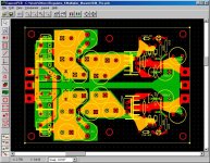
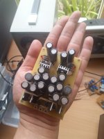
First it was a catastrophic failure - the rectifier diodes on the PCB drawing (the one I published earlier) have the polarity swapped. All of the newly bought 16 x Panasonic FR (argubly the best of the best) capacitors 25V/1200uF went to heaven. I trashed the whole board and kept only the ceramic capacitors, inductors and ferrite beads, and the rectifier diodes.
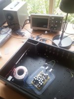
Now it is working fine on a new board. I have turned it on and off a few times and there has been no smoke. With the way I tuned it using 1 x 1N4148 and 6k8 resistor, the voltage drop is about 1.3V, which is possibly the lowest voltage drop achievable with the KM. I can't see any ripples at the output with my 100MHz digital oscilloscope, only noise at the noise floor. Measurements matched the specification / LTSpice simulations.
For purpose of testing, I used 680R at the output which drew 25mA current only. The voltage at the first C of the CLRC after the recifier bridge was at 18.3VDC from my multimeter. The red LED was brightly lighted at turned on, and fade away within 4 seconds. The voltage at the output was initially at 16.5VDC a few seconds after turned on, and slowly reaches at 17VDC after about a minute.
The PCB does not have silk screen layer so soldering is slightly less convenient. It was the first time I tried ExpressPCB and did not know the default gap between the ground / power plane and component pads was rather small so soldering is once again requires much care. I used a magnifier to examine the board to be sure it has no shorts after the built. This is a lesson I have learnt. I won't be using ExpressPCB from this point on as I have bought Sprint Layout 6 for future printed circuit board work. Though I have to confess ExpressPCB is probably the easist to use.
Regards,
Bill
First it was a catastrophic failure - the rectifier diodes on the PCB drawing (the one I published earlier) have the polarity swapped. All of the newly bought 16 x Panasonic FR (argubly the best of the best) capacitors 25V/1200uF went to heaven. I trashed the whole board and kept only the ceramic capacitors, inductors and ferrite beads, and the rectifier diodes.
Now it is working fine on a new board. I have turned it on and off a few times and there has been no smoke. With the way I tuned it using 1 x 1N4148 and 6k8 resistor, the voltage drop is about 1.3V, which is possibly the lowest voltage drop achievable with the KM. I can't see any ripples at the output with my 100MHz digital oscilloscope, only noise at the noise floor. Measurements matched the specification / LTSpice simulations.
For purpose of testing, I used 680R at the output which drew 25mA current only. The voltage at the first C of the CLRC after the recifier bridge was at 18.3VDC from my multimeter. The red LED was brightly lighted at turned on, and fade away within 4 seconds. The voltage at the output was initially at 16.5VDC a few seconds after turned on, and slowly reaches at 17VDC after about a minute.
The PCB does not have silk screen layer so soldering is slightly less convenient. It was the first time I tried ExpressPCB and did not know the default gap between the ground / power plane and component pads was rather small so soldering is once again requires much care. I used a magnifier to examine the board to be sure it has no shorts after the built. This is a lesson I have learnt. I won't be using ExpressPCB from this point on as I have bought Sprint Layout 6 for future printed circuit board work. Though I have to confess ExpressPCB is probably the easist to use.
Regards,
Bill
Attachments
Your voltage drop is too high for some reason. My troubleshooting section here might be helpful:
The K Multiplier
The K Multiplier
Voltage across R2 is 0.25v so i guess the sa1306 is faulty or possibly a fake one. The hfe of sa1306 i measured was 195. So i will order some 2sa1930 from Mouser
I've done some small updates on my Kmultiplier page linked to in my signature. I had planned on doing this for a long time, but when I went to do it I realized I'd forgotten what all I needed to update.
So if you see of something that should be there or something that's not right, let me know.
So if you see of something that should be there or something that's not right, let me know.
You can see the ESR of C1 as the bottom part of a resistive divider with R2. So for the average lytic, a 1k/50m divider means 86db filtering at C1. The Kmultiplier gets 76db at most, so in the worst-case scenario a cap with 100mR ESR will reduce filtering by 1/5. The average lytic will probably do pretty well, and going below 50mR is at diminishing returns.
I might as well add this to the Kmultiplier page.
I might as well add this to the Kmultiplier page.
ESR should matter very little for C3, but you would want it to be as low as possible to improve filtering, just like any PSU cap closer to the rectifier.
 thanks!
- Home
- Amplifiers
- Power Supplies
- Keantoken's CFP cap multiplier