Goon morning EddieT,
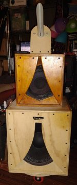
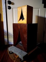
that's my K-tube + fieldcoil driver in it's latest version.
See also: https://www.diyaudio.com/community/threads/fieldcoil-k-tube.363723/page-6
Has been working nicely for some years now. Can't really improve further so my attention at this moment is more directed to the other drivers.
Regards, Reinout

I made a small cajon from a sturdy cardboard cat litter box by pouring the litter out an elliptical hole. Seeing this Cajon in a street band (Stray Melody) on YouTube got me wondering if a Karlson cajon has ever been designed?

I somehow doubt its been done - but possible (K-ajon) - but when tapping on an empty PA130 "XKi" (made of 9mm Baltic birch plywood) there are tonal possibilities: tapping on the wings , back - etc.- varying the cutout area with palm - varying the slot. With a piezo contact pickup the little box could probably make a fun percussion instrument when amplified.
On the Karlson horizon - I'm not seeing much action but do know Suntiger builds intriguing K-hybrids such as K/open back combo and 1/4 wave K with rear horn loading vs traditional bandpass K. Also he does concentric K-tube work - SO - don't be afraid to try new things.
I'm interested in multi-way-K - to have a "musical" speaker system which also is basically more free from intermodulation distortion than FR, and- coax/2-way.
It would be nice to see some midrange -K modules as its
easy to make K-tube and XKi such as say an 18" speaker in an XKi enclosure no more than 24 inches tall.
Attachments
hello everyone, can you help me understand something?.
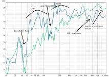
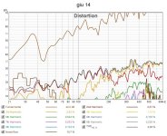
I made some measurements of a K12 prototype (woofer only).
for comparison I measured the 12" woofer in free air with no enclosure inside a small room and then I measured K12 , also in the same small room.
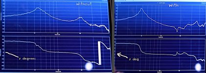
as you can see from the first graph there are 2 important cancellations, one at 45Hz and the other at 150Hz.
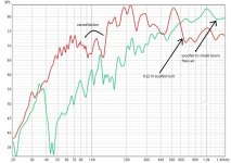
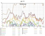
subsequently I made a measurement of K12 in a large 700-seat auditorium and the second graph came out.
as a result I deduced that the cancellation of 45Hz was due to the small room but the one around 150Hz remained, I can't figure out what caused the latter. perhaps from the posterior chamber or perhaps from the anterior chamber. I thought of applying a diode on wire R which goes from the sound card to the amplifier and then making two measurements, one for the direct radiation and another for the rear radiation which crosses the reflex ports and enters the front one. I'm afraid the speaker won't work well this way though.
Do you know any tricks to find out the cause of this problem?.
I made some measurements of a K12 prototype (woofer only).
for comparison I measured the 12" woofer in free air with no enclosure inside a small room and then I measured K12 , also in the same small room.
as you can see from the first graph there are 2 important cancellations, one at 45Hz and the other at 150Hz.
subsequently I made a measurement of K12 in a large 700-seat auditorium and the second graph came out.
as a result I deduced that the cancellation of 45Hz was due to the small room but the one around 150Hz remained, I can't figure out what caused the latter. perhaps from the posterior chamber or perhaps from the anterior chamber. I thought of applying a diode on wire R which goes from the sound card to the amplifier and then making two measurements, one for the direct radiation and another for the rear radiation which crosses the reflex ports and enters the front one. I'm afraid the speaker won't work well this way though.
Do you know any tricks to find out the cause of this problem?.
Attachments
Is the 1cm thick cardboard that I used to build the rear chamber absorbing energy at a frequency around 150Hz?
possibly - K12 depending on whether a tight lowpass gap is used needs 18mm plywood for the back panel. 12mm plywood in my Kube12 has some flex but no suckout. The inner vent and vent's position can make dips. What does your K12 look like? - got any pictures ?
my Kube 12 has dips- with one around 380Hz - it sounds really good with a cheap 2.1 amplifier and Pianolydia's "K3.5 / 3FE25 mini speakers
my Kube 12 has dips- with one around 380Hz - it sounds really good with a cheap 2.1 amplifier and Pianolydia's "K3.5 / 3FE25 mini speakers
Attachments
but certainly freddi.
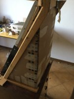
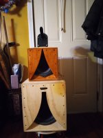
I tried to make it modular as much as possible in order to do many tests and experiment.
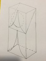
as you can see from img_1 , the rear chamber has a triangular shape and is made of 1cm thick corrugated cardboard , while the front chamber is made of wood .
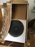
the surface that houses the woofer is made up of 2 segments, one fixed in wood (below) and the other removable in cardboard (above).
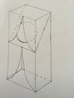
however as you can see from the photo img_2 both segments lie on the same plane. it is not made like a classic K12 in which the upper half has a certain angle of inclination with respect to the panel below which houses the woofer.
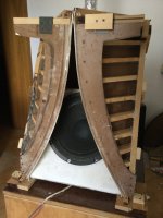
here there is no classic reinforcement shelf that divides the lower segment from the upper one (img_ 3 ), perhaps it is also for this reason that there is a hole in the graph around 150Hz .
reading on the official karlson site I read that the reflex ports work below 130Hz.
http://home.planet.nl/~ulfman/artic/kkoppler/kkopl_en.html (fig.2)
perhaps the hole occurs for this reason, but if it were so there should be no gain above this frequency, which is present and is shown in the graphs that I have already posted (but my piece of furniture is 60cm tall so maybe it's not even this is the reason, who knows).
I've used REW to see what my room's modes are but I've noticed that at 150Hz there are no particularly powerful cancels.
these are the measurements of my room: length 4.45m width 3m height 2.7m.
when I listen to this K12, on the first floor, even at low volume and at a certain frequency, the floor vibrates.
I tried to make it modular as much as possible in order to do many tests and experiment.
as you can see from img_1 , the rear chamber has a triangular shape and is made of 1cm thick corrugated cardboard , while the front chamber is made of wood .
the surface that houses the woofer is made up of 2 segments, one fixed in wood (below) and the other removable in cardboard (above).
however as you can see from the photo img_2 both segments lie on the same plane. it is not made like a classic K12 in which the upper half has a certain angle of inclination with respect to the panel below which houses the woofer.
here there is no classic reinforcement shelf that divides the lower segment from the upper one (img_ 3 ), perhaps it is also for this reason that there is a hole in the graph around 150Hz .
reading on the official karlson site I read that the reflex ports work below 130Hz.
http://home.planet.nl/~ulfman/artic/kkoppler/kkopl_en.html (fig.2)
perhaps the hole occurs for this reason, but if it were so there should be no gain above this frequency, which is present and is shown in the graphs that I have already posted (but my piece of furniture is 60cm tall so maybe it's not even this is the reason, who knows).
I've used REW to see what my room's modes are but I've noticed that at 150Hz there are no particularly powerful cancels.
these are the measurements of my room: length 4.45m width 3m height 2.7m.
when I listen to this K12, on the first floor, even at low volume and at a certain frequency, the floor vibrates.
Attachments


qualcuno sa dirmi qual è l'angolo di irraggiamento della klam rispetto al suo asse? , e quale invece di K15?
Attachments
Last edited:
Please arivel, write in English:qualcuno sa dirmi qual è l'angolo di irraggiamento della klam rispetto al suo asse? , e quale invece di K15?
"can someone tell me what is the radiation angle of the klam with respect to its axis? and which instead of K15?"
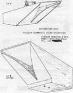
I think the lower section would be tuned pretty high including its 1/4 wave.
There was similar (sans front lens) built:
https://www.diyaudio.com/community/threads/lowes-fullrange-soundbody-s.155671/
If I were doing per drawing then would consider making the bottom K-section with a separate woofer and perhaps as sealed rear chamber. The upper section could be sealed / aperiodic vented.
here's a demo I believe of NEXO's k-slotted shelf vent technique to improve response smoothness. Whether it would work well in a Karlson type = ?
That duct just looks like sensible non-parallel walls and a way to "tap" at one location and terminate at another. The lump in the corner reminds me of Roy's mumps in his horns. I don't know what we can make of it (bec so much is going on), but I liked the link and I don't know how you keep finding this stuff, Fred! 🙂
Attachments
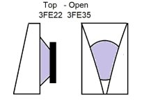
I'd like a 3D printed K for 3FE35 - as small as possible for a tweeter module.
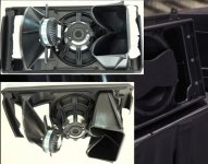
Here's some K-tweeter setups I can do showing two on top of an XKi 8 with Eminence Beta 8A: The big tube is by Suntiger and driven by a 3FE35 as is the K3.5.
The 3-way is Eminence Kappa12a - B&C PL21 and a Transylvania Power Company "The Tube"
Here's some K-tweeter setups I can do showing two on top of an XKi 8 with Eminence Beta 8A: The big tube is by Suntiger and driven by a 3FE35 as is the K3.5.
The 3-way is Eminence Kappa12a - B&C PL21 and a Transylvania Power Company "The Tube"
Attachments

I'm pretty well stuck w/o tools - maybe someone might try K-cone tweeter as so.
I ran a Lavoce 3" in a cardboard lens with
some "shading" of the cone by the aperture - no
measurements and probably not 120 degree horizontal dispersion, but was very "holographic".
6mm plywood might be good then experiment with cardboard or foamcore til meaurements or/and subjective results are good. You need a rising on-axis response driver imo.
A similar cardboard lens and Dynavox copy of the old CTS "phenolic ring tweeter" gave 120 degree dispersion.
Attachments

Last edited:
HI .
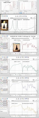
I expected that the driver inserted in my Karlson K12 cabinet would reduce harmonic distortion but what I see in the graphs is the opposite.
What do you think I did wrong?
I expected that the driver inserted in my Karlson K12 cabinet would reduce harmonic distortion but what I see in the graphs is the opposite.
What do you think I did wrong?
Attachments
One thing you need to do is high pass the Karlson at 65hz to avoid overexcursion of the driver below the point that the box begins to unload. I have a Karlson K15 and when I tried to run the box without any high pass at 60 hz, the sound turned to mush. That might not happen if the driver has high x-max, but I use EV 15L drivers which only have 3 mm xmax, so prone to distorting when trying to reproduce lower frequencies. I use a subwoofer below the Karson.
Retsel
Retsel
HI .
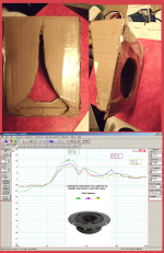
Do you know how they visualized air turbulence in wind tunnels?
they attached many very light pieces of thread that moved with the air and in this way it was possible to understand what was happening.
this was done to improve the aerodynamics of automobiles.
I wonder if it is possible to do the same thing for the exponential aperture by putting the wires on the edge. perhaps it is better to use a small range of frequencies at a time rather than a complete sweep.
I don't know if you can see anything, what do you think?
- Home
- Loudspeakers
- Full Range
- Karlson