As the title says, I found a nice HP 333A locally on Craigslist for $25 and although I already have a QA400 I thought why not at that price. The unit is quite clean and the guy I bought it from told me he picked it up from the lab that he worked at where they were getting rid of a bunch of old equipment. The RMS voltmeter is pretty much spot on and works great, the distortion meter however is not working all that great.
I tested it on one of my Aleph's and the QA400 was showing about .12% distortion under test where the 333A shows about .7% distortion. The unit nulled the signal manually and it seemed that the auto nulling was working fine as well when it was switched in.
I have searched the net a bit and I have the service manual. I noticed that a lot of people are replacing the dated electrolytics. A quick glance in mine shows a lot of 1975 date codes on the caps. I'm going to go through the steps outlined in section 5-40 of the manual for troubleshooting the distortion function. I was just wondering if some of you folks that are quite familiar with the HP equipment have any tips or things to check when the dist. meter is out of line?
The question is which one tells the true the QA400 or the HP333A ?
I have a HP333A, a HP334A and a Roland Quad-Capture Sound card that I use with MatLab.
Testing a 1 KHz Sinusoidal signal at 1 VRMS from my Leader LAG-120 is giving me : 0.02% THD from both HPs and the sound card. The LAG-120 THD specification is <0.05%. So it seems consistent.. But..
The least reliable test gear out of the three for me is the sound card. I ended up using MatLab with the sound card to get a better control over the measurements. Looking at the frequency response of the QA400, I recognise my Roland Quad-Capture..
Following the HP alignment guidelines has been beneficial for me. The photoresistor and lamp alignment had a significant impact on my HP333A automatic nulling capacity.
By the way, have you opened the cover to look inside? Isn't it a nice piece of equipment !
It could also be that the HP 333/334 are measuring THD+N and the QA400 is indicating just the THD. The THD+N will always be higher.
THx-RNMarsh
THx-RNMarsh
Although I used that instrument in some prior incarnations, I know nothing about its internal architecture nor implementation. I suggest you start familiarizing yourself with the instrument by reading through the material collected and presented by Dick Moore, e.g. http://moorepage.net/THD.html , http://www.moorepage.net/334.html et seq. Since he is recently deceased (see http://www.diyaudio.com/forums/equi...ntributor-richiem-dick-moore.html#post4511882 ) I don't know how long this excellent collection of articles will be available.. . . . I was just wondering if some of you folks that are quite familiar with the HP equipment have any tips or things to check when the dist. meter is out of line?
With few exceptions, H-P always made well-designed, durable instruments. While the DMM they give away at Harbor Freight may be adequate to locate a totally failed component, my (unsubstantiated) gut instinct says that it may require test equipment of comparable quality to the '333 to locate and correct the many small degradations that have accumulated over time and now compromise your '333's performance. But as Richard Marsh ( http://www.diyaudio.com/forums/members/rnmarsh.html ) documented in a series of posts scattered through the "Low-distortion Audio-range Oscillator" thread ( http://www.diyaudio.com/forums/equipment-tools/205304-low-distortion-audio-range-oscillator.html ), it is sometimes possible to IMPROVE some "outdated" instruments beyond their original performance levels.
The superannuated electrolytic capacitors are certainly candidates for replacement. Even if they still have "factory-new" characteristics, many modern electrolytics will be superior. Whether or not this will make a difference to your '333 is a different question.
Before I took on the task of capacitor replacement, or a full service-manual alignment procedure, I'd use my 'scope (and spectrum analyzer!) to look at the "Residual" signal output - and compare it to the residual signal from your QA400, or other instruments. This can give you a clue as to whether the '333 is being compromised by un-nulled fundamental, distortion products being created within the instrument itself, broadband noise in the electronics, or power supply noise and ripple.
And please keep us posted with what you find!
Dale
Okay sorry to take so long to post back. For some reason I received no notification of follow up posts on my thread, that's never happened before.
I've had some time now to play with this 333a some more. In addition to my DIY Alephs I also tried measuring the distortion of my Hafler XL600 amplifier. It is the best measuring amplifier (recently .014% at 312W output with the QA400) in my system and it too measured about .7% distortion on the 333a. I then tried feeding the oscillator output of the QA400 at various intensities of .1V - 1V rms into the 333a and I have approx. 0.7% distortion shown at any given audio frequency from 20 - 20khz. So it certainly appears that the 333a is the source of the issue.
I then started on the distortion function troubleshooting section of the service manual which led me to the wein bridge checks. A couple of the resistances were off for the wein bridge by about 30% so I spent an evening getting that adjusted back to no more than about 15% at the highest. Boy that was fun! I ended up turning the lights out in the shop and wearing my headlamp with red LED illumination to perform that setup. However even after going through that the distortion readings remain the same.
I decided to check the RMS meter calibration to see if that was working properly and aside from a small adjustment that was needed at the 400Hz setting it measures RMS volts quite well all the way out to 2.2 MHz, which is the limit of my el-cheapo benchtop oscillator. I had a to use my scope to match output levels from the benchtop oscillator to the 333a at the various measured frequencies.
Just to quell any questions nagging at me from the back of my mind about the power supply. I checked the +/- 25vdc outputs with the scope. The +25v seemed a good bit noisier than the -25v. I pulled the 40uF cap that was right after the +25v regulator and it was measuring bad at < 1uF, where the -25vdc cap was still measuring about 41uF. I changed both of them out with a pair of new 47uF axials that I had in my spare parts bin. Noise on both rails seemed now equal and low. I also went ahead and changed out the 200uF/50V caps right after the bridge rectifier with some 1000uF/80V caps. Unfortunately this had no effect on the distortion measurement, still ~ 0.7% displayed.
One thing I noticed yesterday about the time I needed to walk away from the 333a for the day was that the auto tuning is not working at low frequencies. I tried switching the auto tuning in at 400hz and it quickly mistunes. At 1khz and above the auto tuning holds the fundamental fine. The bad thing is that I'm not sure if this was present before I began my adjustments or not because I only tried auto tuning at 1khz and above in the early stages.
In skimming through most of the cal procedures it looks like I will have to be creative for some of them with what I have available to me here at the house. In addition to the aforementioned QA400 my current benchtop test equipment includes a Hitachi V-1060 100MHZ scope, Uni-T 61E and Fluke 77III DMM's, Beckman FG2 2 mhz oscillator and a BK precision 878 LCR meter. The FG2 oscillator is anything but low noise, so I have to rely on the output of the QA400 either directly or fed through an amplifier for my distortion measurement purposes.
DAsutton - You are correct this HP is a very nice piece of equipment, build quality on the interior matches the exterior. It looks like an old rugged piece of ex-military gear. Anyway, Now if I can just get the distortion measurement to look as good as the aesthetics I'll really be happy. 🙂
Last edited:
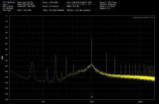
I ran a check on the 333a tonight with the QA400 oscillator connected to it. I attached the picture of the residual output to the QA400 from the 333a. The left channel is of course the residual and the right channel is showing the QA400 in loopback.
Nasty yes?
Nasty yes?
Attachments
By any chance, do most of those spectral lines fall at odd multiples of the power line frequency?
Dale
Dale
By any chance, do most of those spectral lines fall at odd multiples of the power line frequency?
Dale
Dale,
Just a quick glance at it looks like yes they do fall on the odd power line multiples.
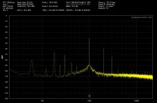
I ran through the wein bridge balance procedure again which brought the fundamental down a good bit now after tuning. Picture attached.
Attachments
Hi Chamberman,
I am away from home during the week. I can't make any measurements right now that we could use for comparison.
This weekend, I will try to reproduce the residual output measurement that you made. I will post it for comparison purpose.
I looked for the THD specification of the Hafler XL600. From what I found, I think that it is more likely to measure around 0.08% THD or a little bit better from this amplifier.
Since that the XL600 is of a certain age, I guess that the 333A measurement would match with that kind of performance.
Measuring 0.014% with the QA400 from the XL600 is questionnable for me. I am not sure if it is realistic and what it represents. It seems far out. At a point that I don't know if it is a valuable measurement.
DAsutton,
That would be great if you could post your residual measurements. The .014% reading on my XL-600 was at 312 watts out, at 200 watts it was .011%.
On a good note I made a little bit of headway tonight. I decided to go ahead and replace ALL of the power supply capacitors. The residual cleaned up quite a bit. The two pictures posted are just before and then right after the PS capacitor replacement.
Also the low frequency 400hz auto mistuning issue I spoke of earlier cleared up with the second wein bridge balance procedure that I performed the other evening.
Attachments

Hi Chamberman,
Since that the XL600 is of a certain age, I guess that the 333A measurement would match with that kind of performance.
Measuring 0.014% with the QA400 from the XL600 is questionnable for me. I am not sure if it is realistic and what it represents. It seems far out. At a point that I don't know if it is a valuable measurement.
Why are you including a piece of audio gear in your evaluation of the 333A?
The traditional means for evaluating measurement gear is to hook a signal output to its signal input and measure the residual distortion of the simple short cable doing the connecting, which is usually far closer to zero than that of any piece of gear with greater complexity and active components, such as a power amp.
I haven't seen or touched a 333A since I was a university student in the middle 60s and early 70s, but the first thing I did at the time is hook its input directly up to the output of the best audio signal generator available to me, and run standard tests to observe their joint residual distortion.
That has been the first thing I did to every successive piece of audio measuring gear.
See post #5. DAsutton was responding to some measurements I had performed. The XL 600 was being used because it was the best measuring amplifier I have according to my QA 400. The amplifiers were tested first because I was curious as to how close to the QA400 they would measure. Once I realized the distortion measurements were too high I began using the low noise oscillator from the QA400 fed into the 333. The pictures that were posted are the residual from the QA400 low noise oscillator being fed into the 333a.
Last edited:
Hi Chamberman,
I made some mesurements with my HP333A. From what I can see, this unit is untouch, all parts are original.
The residual signal that I measured is from the point identified as 'J2'.
Refer to : HP333A DIAGRAM.pdf.
MEASUREMENT #1
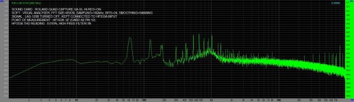
I submitted the HP333A to a 1 kHz sinus and took a FFT from the HP333A input. See FFT HP333A INPUT.jpg for more details.
MEASUREMENT #2
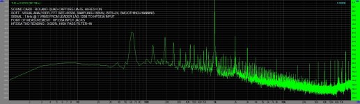
I took the FFT of the residual signal at J2.
For a better visual comparison, I just moved the probe without adjusting anything else. I haven't resized the FFT. I haven't modified the sound card gain, etc.
From my point of vue, the fondamental frequency is 'gone'. The shape of the frequency content is similar to the one from measurement #1. It is a little bit cleaner in term of the number of frequency spikes.
Note the presence of the harmonics 2,3,and 4. They are recognisable in both measurement #1 and #2.
(FFT HP333A J2.jpg)
MEASUREMENT #3
I turned off the generator to look at the residual signal at J2. 2nd, 3rd and 4th harmonics are gone. The HP333A is reading 0.01% THD with no signal applied.
(FFT HP333A J2 NO SIGNAL.jpg)
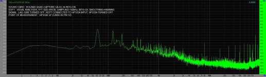
MEASUREMENT #4
I turned off the HP333A. I took the FFT keeping the probe at J2 without adjusting or changing anything else.
(FFT HP333A OFF.jpg)
MY CONCLUSION
Taking a FFT of the residual signal at J2 with a sound card provides some information.
We can visualise the nulling performance..
I will do the same test with the HP334A to see how it compares.
Due to the limitations of the sound card, I will continue making measurements with an oscilloscope.
I made some mesurements with my HP333A. From what I can see, this unit is untouch, all parts are original.
The residual signal that I measured is from the point identified as 'J2'.
Refer to : HP333A DIAGRAM.pdf.
MEASUREMENT #1
I submitted the HP333A to a 1 kHz sinus and took a FFT from the HP333A input. See FFT HP333A INPUT.jpg for more details.
MEASUREMENT #2
I took the FFT of the residual signal at J2.
For a better visual comparison, I just moved the probe without adjusting anything else. I haven't resized the FFT. I haven't modified the sound card gain, etc.
From my point of vue, the fondamental frequency is 'gone'. The shape of the frequency content is similar to the one from measurement #1. It is a little bit cleaner in term of the number of frequency spikes.
Note the presence of the harmonics 2,3,and 4. They are recognisable in both measurement #1 and #2.
(FFT HP333A J2.jpg)
MEASUREMENT #3
I turned off the generator to look at the residual signal at J2. 2nd, 3rd and 4th harmonics are gone. The HP333A is reading 0.01% THD with no signal applied.
(FFT HP333A J2 NO SIGNAL.jpg)
MEASUREMENT #4
I turned off the HP333A. I took the FFT keeping the probe at J2 without adjusting or changing anything else.
(FFT HP333A OFF.jpg)
MY CONCLUSION
Taking a FFT of the residual signal at J2 with a sound card provides some information.
We can visualise the nulling performance..
I will do the same test with the HP334A to see how it compares.
Due to the limitations of the sound card, I will continue making measurements with an oscilloscope.
Attachments

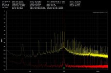
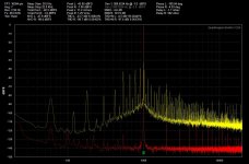
DASUTTON, Thanks for posting your results. I had some time tonight and ran a couple of the same spectrum scans on mine.
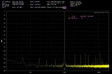
The first is the QA400's output measured at the 333a input terminals.
The second is the output at J2 with no nulling.
The third is the nulled output.
I do not think that my spectrums are that far off from yours. My 333a nulling is not as good as yours which appears to be around -50db where mine is around -44db.
Where my 333a is vastly different is in what the analog front panel meter is reading. Its showing about .5% for both the QA400 and Beckman oscillators.
Attachments
Chamberman,
The 'A6' card, literally the 'black box' in the HP333A is a key component for the automatic nulling function.
I wonder how it looks like inside the box for your HP333A and how it compares with the specifications.
In mine, there is some rubber mousse holding the lamps and the photo cells in place. The rubber mouse had degraded by the time.
There was some residuals sticking to the lamps and the photo cells that I remove with isopropyl alcohol.
The resistance readings of the photo cells were off compared to the values specified in the HP service manual.
I think that it is benificial to get some symmetry in how the photo cells are reacting to the light.
The adjustements are purely mechanical. It consists in moving around and twisting the components to get the resistance measurements as specified.
Yeah I went through the "black box" twice and on the second go-around I got the resistances for the photocells to within 10% of the values stated in the service manual. The manual says < 20% is good so I would think I'm well within the values needed. The black rubber foam in mine is getting a bit stiff but is still holding up okay and the lamps were clean.
I've seen references to people saying they get -70db or more nulling of the fundamental out of these old HP's so something certainly seems amiss.
I've seen references to people saying they get -70db or more nulling of the fundamental out of these old HP's so something certainly seems amiss.
After a lot of dabbling with this 333a I think I may have pinpointed the issue. I believe the problem was with the A3 pcb. As I said before the voltmeter function works great and the auto tuning works good as well. I noticed that when doing distortion measurements there was some spurious noise where the needle would jump up slightly every 15 - 20 secs or so, like a leaky transistor. I went through and replaced all of the caps on the A3 pcb which had no effect.
I then replaced Q1 (a 2N3904) on the A3 pcb. It is the input transistor for the preamplifier, there was no change in the measured noise level. I pulled Q2 and checked the hFE = 110 then Q3 hFE = 12. That hFE for Q3 seemed extremely low. Q5 on the bridge amplifier is the same PN as Q3 so I pulled it and the hFE = 60 for Q5.
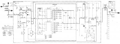
So based on the extremely low hFE it looks like Q3 on the preamplifier is going bad. That transistor is a Motorola custom PN 4-354-536. Anyone got any ideas on a possible replacement?
I included the schematic of the A3 pcb.
I then replaced Q1 (a 2N3904) on the A3 pcb. It is the input transistor for the preamplifier, there was no change in the measured noise level. I pulled Q2 and checked the hFE = 110 then Q3 hFE = 12. That hFE for Q3 seemed extremely low. Q5 on the bridge amplifier is the same PN as Q3 so I pulled it and the hFE = 60 for Q5.
So based on the extremely low hFE it looks like Q3 on the preamplifier is going bad. That transistor is a Motorola custom PN 4-354-536. Anyone got any ideas on a possible replacement?
I included the schematic of the A3 pcb.
Attachments
The service manual is also refering to another manufacturer part number : S24817.
This seems to be a Si NPN transistor formerly produced by Fairchild.
Some web sites are providing the following description : Metal case TO-52, Vce 15 V, Power Rating 360mW. (Seems low for a transistor submitted to 10V Vce continuously...).
Just for testing, why not using a smal signal transistor such as the 2N3904 ?
There are a lot of selector switches around this circuit. My HP333A nulling function was erratic at first. I had to clean all the contact switches. Thanks to the high quality of the components. All contacts came back bright and clean with no efforts and the instrument is very stable since.
Hello DASutton,
Thanks for the suggestions. Over the weekend I tried installing both a 3904 and a 3903 into the locations with no luck. The 3904's I have measure an hFE of about 200 where the 3903's hFE is about 110 so I thought they might be a possibility as well, but no luck. The nulling is completely non-functional with either of those transistor's installed.
I've been through the switches about 3X now using a q-tip dipped with pcb cleaner and no lubricant. They initially had some type of medium consistency grease that had turned brown with age. I have them extremely clean now.
I got tired of messing with it yesterday and made an offer on a "parts or repair" HP 334A off of everyone's favorite auction site. So I have that one on the way now. My take on it is that although I may have to combine two to get one good functional unit, I'll still have less than $150 in the pair and will have spare parts if I need them in the future.
Anyway, we'll see the 334A may come in and be 100% functional. I'm guessing if anything it'll need one or both of the wein bridge lamps replaced and I've got that module set up and ready to go in my 333A so I can swap it over if that's the case.
I received the 334A that I bought off of auction. Checked it out and everything looks good, the meter is broken loose from the panel but other than that it works great. I opened it up and the wein bridge lamps are both working. The rotary switches look like brand new, no gunk on them and almost no visible wear/tracks in the wafers. So I connect my QA400 and put a 1V rms, 1 khz signal into it, the RMS meter measures spot on. Check the distortion and guess what. .55% distortion shown on the 334A.
Now I'm really baffled. 🙁
One thing I noticed is that even when I turn off the QA400 generator I still have > .5% distortion shown on the 334A even with no signal generated from the QA400. Even closing the QA400 software will not alleviate the .5% distortion reading. This distortion remains until I finally pull the USB plug to the QA400. Once I pull the USB plug to the QA400 the distortion completely drops in fact I can range the 334A down to the lowest distortion setting and I only show .07% distortion.
Connecting my function generator and sending the same 1V rms/1 kHz signal to the 334A nets me a .45% distortion reading, this is lower than the QA400 (.55%) and I know that cannot be. I know the QA400 is working properly as loopback still shows a very low .001% on the QA400 and I used the QA400 to check a preamplifier yesterday and it measured just about exactly as rated in the manufacturer specs.
So what am I doing wrong here? I'm failing to take something into account of this I'm sure. I'm using a standard 3' BNC cable to a BNC to banana adaptor to connect the QA400 to the 334A.
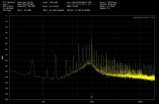
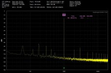
The good news is that the 334A does appear to be operating much better overall than the 333A that I bought locally. The output spectrum of the 334A is much cleaner than the best spectrum I was able to get out of the 333A. I attached the spectrum as measured by my QA400.
Now I'm really baffled. 🙁
One thing I noticed is that even when I turn off the QA400 generator I still have > .5% distortion shown on the 334A even with no signal generated from the QA400. Even closing the QA400 software will not alleviate the .5% distortion reading. This distortion remains until I finally pull the USB plug to the QA400. Once I pull the USB plug to the QA400 the distortion completely drops in fact I can range the 334A down to the lowest distortion setting and I only show .07% distortion.
Connecting my function generator and sending the same 1V rms/1 kHz signal to the 334A nets me a .45% distortion reading, this is lower than the QA400 (.55%) and I know that cannot be. I know the QA400 is working properly as loopback still shows a very low .001% on the QA400 and I used the QA400 to check a preamplifier yesterday and it measured just about exactly as rated in the manufacturer specs.
So what am I doing wrong here? I'm failing to take something into account of this I'm sure. I'm using a standard 3' BNC cable to a BNC to banana adaptor to connect the QA400 to the 334A.
The good news is that the 334A does appear to be operating much better overall than the 333A that I bought locally. The output spectrum of the 334A is much cleaner than the best spectrum I was able to get out of the 333A. I attached the spectrum as measured by my QA400.
Attachments
- Home
- Design & Build
- Equipment & Tools
- Just picked up an HP 333A got a few questions