What filters are you using for the THD?
My knee-jerk reaction is that some power line-related corruption is getting into your test signal. Possibly within the generator itself, but more likely through ground loops, currents in the cable shields, poor quality shields, inductive pickup, etc.
The spectrum plot you posted shows quite a few power-line harmonics. While they don't dominate the (THD + N) measurement, their net contribution is just a dB or two below the contribution from the second harmonic.
I believe we observed a similar situation when you posted a spectrum plot from the '333A, back near the thread's start.
Dale
What filters are you using for the THD?
There should be no filters as the QA400 oscillator is being fed directly into the 334A. I believe the 334A is displaying THD+N, correct?
I thought about the ground loops as well, but the USB thing doesn't make sense. As I said the .55% THD+N displayed on the 334A doesn't show up until you bring up the QA400 software and then generate a signal out to the 334A. Then shut the QA400 signal generator off and the .5% distortion remains. Close the QA400 software and even when the QA400 loses the red "link" light the .5% THD+N displayed by the 334A remains. Once I pull the USB cable the .5% THD+N shown by the 334A drops to nothing (~.07% THD+N). If I immediately plug the USB cable back into the laptop the THD+N on the 334A remains at .07%. I would expect that if it were a ground loop causing the issue then just reconnecting the QA400's USB cable would cause the distortion to immediately return. Its not until I reopen the QA400 software and generate a signal out to the 334A that the .5% THD+N shows up again.
Based on what I'm seeing its as though once the QA400 USB driver has loaded and a signal has been generated there is some noise being generated by the QA400.
I may have to go and post on the Quantasylum site to see what they say about this.
The test setup consists of my Win 7 laptop (floating on battery power) operating the QA400 which is connected via a 3' Pomona BNC with a BNC to banana adapter to the 334A.
**Edit for the post from last night, where I typed .07% THD+N should have been .007% THD+N.
I ran some more tests tonight and figured out that the problem lies with the QA400.
I bought a Denon DA-300USB DAC a few months back and I decided to pull it out of my system and use it coupled with True RTA from my laptop as my oscillator. The specs on it are quite good with .0018% THD. I don't know why I didn't think of using it before. Anyway, connecting the Denon DA-300USB to my laptop and feeding a 1khz / 1V rms sine wave to the 334A netted .0135% THD+N. Disabling the sine wave drops the 334A distortion reading to .008% THD+N. This 334A displays .007% - .008% distortion with no signal across the 1 - 20 kHz range, not too bad!
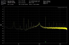
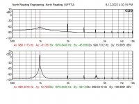
I included a QA400 spectrum from the 334A output with the range set for -60db or .1%. As you can see the second harmonic is the highest and even its down about -100db.
I'm assuming that there is probably very high frequency noise present from the QA400 and due to the fact the 333A/334A have such a high frequency measurement capability (600khz) they are measuring this noise. I still plan to try and get verification on this from QA.
I ran some more tests tonight and figured out that the problem lies with the QA400.
I bought a Denon DA-300USB DAC a few months back and I decided to pull it out of my system and use it coupled with True RTA from my laptop as my oscillator. The specs on it are quite good with .0018% THD. I don't know why I didn't think of using it before. Anyway, connecting the Denon DA-300USB to my laptop and feeding a 1khz / 1V rms sine wave to the 334A netted .0135% THD+N. Disabling the sine wave drops the 334A distortion reading to .008% THD+N. This 334A displays .007% - .008% distortion with no signal across the 1 - 20 kHz range, not too bad!
I included a QA400 spectrum from the 334A output with the range set for -60db or .1%. As you can see the second harmonic is the highest and even its down about -100db.
I'm assuming that there is probably very high frequency noise present from the QA400 and due to the fact the 333A/334A have such a high frequency measurement capability (600khz) they are measuring this noise. I still plan to try and get verification on this from QA.
Attachments
I was able to get the 333A functional again, this is the one that was giving me problems. As I stated before I had found a transistor with extremely low hFE (Q3) on the A3 pcb. I ended up replacing this transistor and Q5 (both were the same part #) on the A3 pcb with 2n3903's.
In checking the new 334A that I just received I found the bias point TP2 on A3 to have a much higher level than the manual recommends. It was set for 22V. TP1 on A3 was set properly at 2.65V. That 334A is working very well so I didn't adjust the bias points. However that got me wondering if the 19.5V I was setting the same point (TP2 on A3) in my 333A was too low. I went back into the 333A and began adjusting the TP2 bias point up from 19.5 and at around 20.5V the fundamental nulling began working again. I ended up setting TP2 at about 21V.
Now the 333A when measuring my Denon DAC shows about .012% THD+N where the 334A measures about .0135% THD+N. When the sine wave is disabled the 333A drops to .007% THD+N where the 334A drops to .008%. The needle is wavering a bit by approximately .001% THD on the 333A where my 334A is stable even at this low level. But the good news is that the 333A is completely usable now and matches up nicely with the stock 334A. So it ended up taking one working analyzer to assist me in getting the first one working again.
I guess the lesson here is if you substitute parts into an original circuit then the original bias points may no longer work! 😀
It is possible that replacing a transistor has nothing to do with this fix.
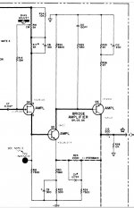
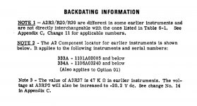
Check the schematic for the A3 card. There is a note beside the test point TP2.
The original bias adjustment was set to obtain -19.5V at TP2.
But from change No. 14 it is specified at -20.2 .
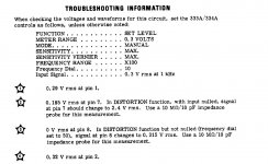
I have included the conditions specified by HP prior to make any voltage and waveform measurements. May be something to think about. But also, what is the value of the reference voltages provided on the schematic if the bias level is changed. All the transistors around are direct coupled.
This small portion of circuit composed of Q4, Q5 and Q6, is ac coupled with the rest. Somehow the bias adjustment seems to affect the AC gain of the circuit.
I would need to simulate the circuit to get a better understanding.
From your experimentation and your results, this setting has a direct influence on the distortion measurement.
You are also able to get the needle down below 0.01% THD with your HP333A and HP334A. This is something that I can’t reproduce. I can’t get the needle(s) below around 0.015%.
I will simulate this part of the circuit with LTSPICE to see what is the impact of the bias change.
Check the schematic for the A3 card. There is a note beside the test point TP2.
The original bias adjustment was set to obtain -19.5V at TP2.
But from change No. 14 it is specified at -20.2 .
I have included the conditions specified by HP prior to make any voltage and waveform measurements. May be something to think about. But also, what is the value of the reference voltages provided on the schematic if the bias level is changed. All the transistors around are direct coupled.
This small portion of circuit composed of Q4, Q5 and Q6, is ac coupled with the rest. Somehow the bias adjustment seems to affect the AC gain of the circuit.
I would need to simulate the circuit to get a better understanding.
From your experimentation and your results, this setting has a direct influence on the distortion measurement.
You are also able to get the needle down below 0.01% THD with your HP333A and HP334A. This is something that I can’t reproduce. I can’t get the needle(s) below around 0.015%.
I will simulate this part of the circuit with LTSPICE to see what is the impact of the bias change.
Attachments
DASutton,
I overlooked the HP note you referenced in regards to later production units.
I had the inclination to reinstall the low hFE transistor back into the 333's A3 pcb the other day, but its working so well I thought I'd leave well enough alone. 😉
I was happily surprised to see the baseline distortion of these being so low. I was just hoping to be < .02%. FWIW the only thing I did to the 334A is adjust the - 25V down a touch, it was at -25.5V. That and wipe all of the switch contacts down with a contact cleaner dipped q-tip.
Oh and the meters mechanical zero was adjusted on both units back to actual zero they were both a good 1/8" below zero when powered off, so that is not skewing the results I'm seeing.
I'm going to add onto this thread... I picked up a 334a and it does not measure distortion correctly (comparing to 2 know good analyzers). I have narrowed down the problem with the A2 board. This board contains the impedance converter and the meter amplifier. I am very sure the issue is with the meter amplifier portion.
The problem is oscillation occurs just before reaching the null point. When I scope the output terminals of the 334a, I can see the waveform as it nulls. Just before the null occurs, oscillation develops in the waveform. The unit will null, but then there is added noise and the meter indicates this because all the measurements are including the noise.
I have a friend that has an identical vintage 334a with the same board revisions. I swapped boards last night and it definitely follows the A2 board. I need to scope around the board and see what I can find. There are two feedback loops, so I'm not sure the best way to identify where the oscillation is coming from.
What I found interesting, is the manuals says this on the A2 meter schematic next to a test point waveform: 'Voltage between collector of A2Q9 and pin 15 (ground) for full scale deflection on the 0 to 1 scale on 0.01V range and above. It cannot be measured on 0.01V range and below because the meter amplifier will oscillate.'
So the meter amplifier will oscillate itself?!?!?!
I will be checking DC values per the schematic to make sure it is accurate.
If anyone has any info, it would be appreciated.
Hi Dave,
Checking the DC voltages sounds like a good starting point. It will tell you if the transistor and resistor specs are in the ballpark.
Also do check the electrolytic capacitors (elco), they are getting old. Do this with an ESR meter! Only change an electrolytic cap if the ESR is high!
Also do check C33, it is a tantalum capacitor, 22uF. Older HP equipment is known to have trouble with tantalum capacitors.
That tantalum capacitor is parallel with an aluminum electrolytic capacitor , C25, with a value of 130uF.
The reason for that was to achieve a low ESR value, what tantalum capacitors do have.
Present day aluminum electrolytic capacitors do have a lot lower ESR than older elcos, so replacing that tantalum with a present day elco should be fine.
If you do not have an ESR meter just parallel a new elco with the one on the board to see if that helps.
That amplifier does have two negative feed-back path, one for DC, the other for the AC response.
That capacitor block (C33, C25) bypasses the DC feed-back path, so the DC feed-back does not influence the AC response. If the bypassing is not "good enough", it might have an influence on the phase shift of the circuit, and consequently on the stability.
MODERATOR: Please turn this last two postings into a new thread, if that is appropriate.
Good luck, Peter
Last edited:
Thanks Peter. A quick update:
The volt meter amplifier was out of calibration on the high frequency end (2MHz Cal). Once this was resolved, the oscillation just before the null disappeared. I performed the device performance verification in the manual and everything measures as the manual states. Really, all of the performance of the unit looks spot on.
I looked at the output of the 334 and my 8903 with the same input signals and the output waveforms via scope or spectrum analyzer look the same. However, the 334 measures differently. I believe the issue is with complex distortion signals. Here is why; with a test solid state amp driven to 1% distortion, the 334 measures this as .5% where the spectrum calculation and 8903 measure 1% (setting the 8903 only to have the 400Hz filter engaged). I then created a two tone signal using 1KHz as the fundamental with a small 2KHz signal as the second signal (2nd harmonic). I tested 10%, 1% and .1% using the 334 and 8903 (and verifying with the spectrum analyzer). The 334 was spot on with the proper measurements.
With the complex distortion, it is measures incorrectly. So is it just my 334?
My A2 board does not have the C33 tantalum installed. I see the through holes, but they are just filled with solder. As far as I can tell, there are no modifications to any of my boards and the caps are original. I did see in the notes about certain components may or may not be installed due to revision changes. The electrolytics have '82 date codes.
Thanks,
Dave
Hi Dave,
Congratulations on fixing your 334!
Looks like HP felt confident about the quality of elcos by the early '80s that they did not use the tantalum cap in parallel!
That HP-8903 sure looks like a nice machine!
The reason for the measurement discrepancies, and your two tone test result, must be because of the voltmeter in the 334. It measures the signal average and is calibrated in RMS volts, that is true only for sinusoidal signals. Measuring complex signals, the residuals of the distorted signal without the fundamental frequency, the residuals are not sinusoidal, the average of it does not reflect an accurate RMS value, only with some error. Hence the difference.
Spectral analysis for distortion measurement takes into account all the harmonics correctly.
If you do not have an ESR meter you should build one for yourself!
I built this one more than 10 years ago: http://members.ozemail.com.au/~bobpar/99_Cent_ESR.pdf
I built the 555 version, for a fixed frequency. It is one my most useful test equipment!
There are lots of other designs around as well.
Regards, Peter
Lamps available for HP333A/HP334A repair
Hi All,
I just bought a box of 10 lamps to replace the burned out lamp in my HP334A (one of the two lamps in the AutoTune circuit). I don't need all 10 lamps and am willing to sell off 6 or 7 lamps at cost if anyone needs them for repair of a HP333A or HP334A.
Mike
Hi All,
I just bought a box of 10 lamps to replace the burned out lamp in my HP334A (one of the two lamps in the AutoTune circuit). I don't need all 10 lamps and am willing to sell off 6 or 7 lamps at cost if anyone needs them for repair of a HP333A or HP334A.
Mike
Old thread response here.
For audio THD+N readings a good working 333A or 334A unit is a nice tool to use, it's a tough unit, literally indestructible. For tube amplifiers, they perfect.
The 400Hz calibration adjustment at 1mV is critical in achieving the highest performance. The calibration requires an AC source capable of a precise 1mV at 400Hz, the A2R34 potentiometer is then adjusted to achieve a 1mV reading at the meter. The source is then set at 300uV for a full scale reading at the highest sensitivity of the meter range. If the unit is able to read between 294-306uV it indicates the unit is operating as well as is possible, i.e. everything is operating a factory new. HP goes as far to recommend the resistor A2R30 to be pulled from the board and replaced if the +/-6uV tolerance isn't met. A Standford Research DS360 ULD signal generator is an AC source that provides the required test signals. If your unit has had work, A2 R30 is the first place to look, on the dozen or so units I've fiddled with over the years, a few had this resistor replaced.
The instrument induced distortion check is another health indicator but requires an ultra-pure sine wave generator or a filtered generator source. The unit will achieve -70dB to the residual if operating well.
Regarding the auto-null feature, the foam pads on the black housing should be removed and replaced with foam tape of similar or a bit thicker. The old pads can be removed by soaking the black box element in electronic grade IPA for a few hours. Replacing the pads will keep the photoresistors from drifting around and also provides support for the lamps.
Re-capping the units. Replacing all the Al-, Ta-electrolytics will run about $300. Use highest quality parts from the usual suppliers.

Re re-capping: It will be quite a bit less if you don't replace the tantalums... they very, very rarely need it. Aluminums yes, tants... hardly ever.Old thread response here.
For audio THD+N readings a good working 333A or 334A unit is a nice tool to use, it's a tough unit, literally indestructible. For tube amplifiers, they perfect.
The 400Hz calibration adjustment at 1mV is critical in achieving the highest performance. The calibration requires an AC source capable of a precise 1mV at 400Hz, the A2R34 potentiometer is then adjusted to achieve a 1mV reading at the meter. The source is then set at 300uV for a full scale reading at the highest sensitivity of the meter range. If the unit is able to read between 294-306uV it indicates the unit is operating as well as is possible, i.e. everything is operating a factory new. HP goes as far to recommend the resistor A2R30 to be pulled from the board and replaced if the +/-6uV tolerance isn't met. A Standford Research DS360 ULD signal generator is an AC source that provides the required test signals. If your unit has had work, A2 R30 is the first place to look, on the dozen or so units I've fiddled with over the years, a few had this resistor replaced.
The instrument induced distortion check is another health indicator but requires an ultra-pure sine wave generator or a filtered generator source. The unit will achieve -70dB to the residual if operating well.
Regarding the auto-null feature, the foam pads on the black housing should be removed and replaced with foam tape of similar or a bit thicker. The old pads can be removed by soaking the black box element in electronic grade IPA for a few hours. Replacing the pads will keep the photoresistors from drifting around and also provides support for the lamps.
Re-capping the units. Replacing all the Al-, Ta-electrolytics will run about $300. Use highest quality parts from the usual suppliers.
+1 on using quality replacements - and cal gear. The equipment used to adjust the unit should have better specs by at least an order of magnitude than the unit being adjusted.
Hal
On the unit I worked, many of the components were removed, it was a donor which I set about to get operating. mechanically and cosmetically good condition. I replaced the wet Tantalums with encapsulated solid type, Vishay and Kemet. They're lower cost with excellent performance. Many transistors were pulled including the germaniums. I have an inventory of HP PNs including some of the specials used on this unit including factory matched. I have a second set of boards for the unit which allowed for some experimentation. One A5 board had all caps replaced and all LTPs matched to quite high precision (repeated runs, fixed temperature). On the other I just replaced the missing components. The result test showed about -3.5dBV of additional rejection on the completely reworked board.
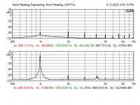
The attached shows 1kHz input at +10.75dBV with rejection to -61.35dBV for -72.1dBV rejection of the fundamental or about .025% THD+N which the meter displayed accurately. The signal is an ultra-pure, 5VRMS sinewave sourced from a Krohn-Hite 6900B distortion analyzer with current calibration. The loop back of the Krohn-Hite shows about -30dBV additional rejection to .001%.
The attached shows 1kHz input at +10.75dBV with rejection to -61.35dBV for -72.1dBV rejection of the fundamental or about .025% THD+N which the meter displayed accurately. The signal is an ultra-pure, 5VRMS sinewave sourced from a Krohn-Hite 6900B distortion analyzer with current calibration. The loop back of the Krohn-Hite shows about -30dBV additional rejection to .001%.
Attachments
Hi Mike,Lamps available for HP333A/HP334A repair
Hi All,
I just bought a box of 10 lamps to replace the burned out lamp in my HP334A (one of the two lamps in the AutoTune circuit). I don't need all 10 lamps and am willing to sell off 6 or 7 lamps at cost if anyone needs them for repair of a HP333A or HP334A.
Mike
you still have the lamps of 0v 14ma? i'm interested in acquiring them. I need 6 of them.
Jorge
Hi, Ihave a 334A which voltmeter and set level are working nice but distorsion in manual and automatic do not null. I think that I have problems in A5 board. I have tested all tantalum caps and they are ok. Voltage of power supply and bias are ok. Do you have any idea of this malfunction?On the unit I worked, many of the components were removed, it was a donor which I set about to get operating. mechanically and cosmetically good condition. I replaced the wet Tantalums with encapsulated solid type, Vishay and Kemet. They're lower cost with excellent performance. Many transistors were pulled including the germaniums. I have an inventory of HP PNs including some of the specials used on this unit including factory matched. I have a second set of boards for the unit which allowed for some experimentation. One A5 board had all caps replaced and all LTPs matched to quite high precision (repeated runs, fixed temperature). On the other I just replaced the missing components. The result test showed about -3.5dBV of additional rejection on the completely reworked board.
The attached shows 1kHz input at +10.75dBV with rejection to -61.35dBV for -72.1dBV rejection of the fundamental or about .025% THD+N which the meter displayed accurately. The signal is an ultra-pure, 5VRMS sinewave sourced from a Krohn-Hite 6900B distortion analyzer with current calibration. The loop back of the Krohn-Hite shows about -30dBV additional rejection to .001%.
Hi Romero,
I believe the only HP333A/334A I've seen in action was at a Test/Repair clinic sponsored by a HiFI shop and the clinic featured a whiz tech from McIntosh. He was fast and I watched him test (and frequently re-tube) a steady stream of ampifiers of many brands, brought by customers. I was an EE co-op student at the time, circa 1967. I clearly remember the fancy lever switch he used to activate Autotune.
This story told to explain I have no familiarity with the 334A, but I have helped a few members successfully troubleshoot their HP339A analyzers. I believe I'd enjoy this challenge.
Would you tell be about the symptoms that lead you to suspect the A5 board?
Sounds like you've already checked the power supplies, so have covered some important basics. I'm guessing you're somewhere in section 5 of the service manual. In any case, would you advise where are in the troubleshooting process, and what you observe at the earliest problematic spot in the signal path?
General questions: same symptoms on all ranges? Do switches "feel" erratic, dirty?
Lastly, would you tell me about a bit your sine wave generator, eg. what frequency range it covers, and distortion performance, if known.
I'm currently traveling but will be in Denver, Colorado tomorrow. What time zone are you in?
Hi Bsst,
My suspect of A5 board is because if I run distortion tests in manual mode I get correct values, but if I turn to automatic mode the meter goes to maximum level.
I run all tests with my dds function generator fy3200 Which shows a 1khz THD of 0.15%.
I have tested lamps and photo sensors and all of them are ok.
Thanks in advance,
Regards.
My time zone is gmt-3 I'm from Rio de Janeiro, Brazil.Hi Bsst,
My suspect of A5 board is because if I run distortion tests in manual mode I get correct values, but if I turn to automatic mode the meter goes to maximum level.
I run all tests with my dds function generator fy3200 Which shows a 1khz THD of 0.15%.
I have tested lamps and photo sensors and all of them are ok.
Thanks in advance,
Regards.
- Home
- Design & Build
- Equipment & Tools
- Just picked up an HP 333A got a few questions