Driving the headphones with the attenuated F4 output occurred to me also. Attenuation is important so that the gain stages are running at signal levels commensurate with "normal" listening through the amplifier and speakers.
Not yet. I ordered some connectors i want to send out with them. It will help with proper wiring.
Driving the headphones with the attenuated F4 output occurred to me also. Attenuation is important so that the gain stages are running at signal levels commensurate with "normal" listening through the amplifier and speakers.
That is a great idea.
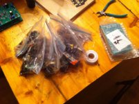
Many have you have received or will soon receive your kits. Please wait to assemnle, as i have some changes that need to be made. Most are simply silkscreen error, but two sple modifications need to be made. I will try ro have documented pics tomorrow evening or Wednesday.
Many have you have received or will soon receive your kits. Please wait to assemnle, as i have some changes that need to be made. Most are simply silkscreen error, but two sple modifications need to be made. I will try ro have documented pics tomorrow evening or Wednesday.
Cool!
Hi buzzforb
Have you shipped the PCBs?
I’m not in a hurry, just want to know.
Best regards,
Doru
Have you shipped the PCBs?
I’m not in a hurry, just want to know.
Best regards,
Doru
PSU BOM(x2):
8 Mur 860 rectifier diodes(Need to be reversed on boards
2 100R (2512) resistors
2 470R (2512) resistors
2 27R (2512) resistors
2 10k (1206) resistors
2 330R (1206) resistors
2 1N4007 diodes
4 1mF 50V caps
8 220uF 50v caps
IRF 610
IRF9610
7824 LDO
7924 LDO
Main Board BOM(x2):
5 470r (1206) resistors
1 100k (1206)
1 220r (1206)
5 10k (1206)
1 2.2k(1206)
1 27r(1206)
1 1M(1206)
1 56K(1206)
1 6.8K(1206)
1 17.8r(1206)
1 49.9R(1206), may be 29r in some cases
4 15r (2512) resistors
1 6.8r(2512)
4 47uF caps
1 10uF cap
1 120 pF smd cap(tiny)
1 50r pot
1 100r pot
2 1k 2W through hole resistors,need to solder to positive lead of 47uF cap rather than designated hole
1 BC560
4 BC550's,The one used in the FE or gain stage needs to be reversed on the pcb. It is on the lower left of the pcb
1 BF862
The only other mod that needs to happen is to jumper the input hole on the FE. As a result, you will have no input signal ground wire hole and will require either linking the ground wire from the input RCA to the ground wire of the output RCA or bringing it back to the FE PSU ground. It is a matter of choice and can be done cleanly either way.
I will post pics of a finished board tonight to show the changes. Feel free to ask any questions.
Last edited:
- Status
- Not open for further replies.
- Home
- Group Buys
- Juma's LSK Preamp - SMD version
