thanks for your interest Sheb,
off note....i wonder why the president/CEO of non-modular pcb design committee hasn't seen this yet!
off note....i wonder why the president/CEO of non-modular pcb design committee hasn't seen this yet!
thanks for your interest, and the support from other people, i will start work soon!
like i said before, fred or xrk, if they get their modular pcbs and test +report result here, my work will be simplified!
reg
prasi
like i said before, fred or xrk, if they get their modular pcbs and test +report result here, my work will be simplified!
reg
prasi
thanks for your interest, and the support from other people, i will start work soon!
like i said before, fred or xrk, if they get their modular pcbs and test +report result here, my work will be simplified!
reg
prasi
I am still waiting for my (modular - mono amp only) PCBs to arrive.
thanks for your interest Sheb,
off note....i wonder why the president/CEO of non-modular pcb design committee hasn't seen this yet!
Yes I have seen it. I am only in when it will be a one board solution. I don't know exactly what is meant by flexibility by using several boards ?! Must be the needed flexible wiring and the flexible extra hours needed to assemble 🙂
Last edited:
I have the BJT boards as well as the original F5HA pcb that I ordered a week or so ago. Unfortunately, my progress isthanks for your interest, and the support from other people, i will start work soon!
like i said before, fred or xrk, if they get their modular pcbs and test +report result here, my work will be simplified!
reg
prasi
 because other family priorities are ahead of my hobbies - take care of the significant half after her shoulder surgery, travel with daughter for her college visits, job hunting etc.
I actually sent a set of BJT and F5HA boards to another member who PM me his interest. He is a college student, and hopefully, he will find some time during the semester or Thanksgiving break and give us some feedback. For the time being, I have measured 100 BC550C and 100 BC560C to use. Hopefully, the universal LM317T pcb's will arrive this week, then I can do more in the long weekend.
Dear Prasi,
Please design a single board but separate the areas such that they can be sawed off later depending on requirement. Join separate areas with jumpers.
gannaji
Please design a single board but separate the areas such that they can be sawed off later depending on requirement. Join separate areas with jumpers.
gannaji
While waiting for my Juma HA boards to arrive I decided to take a try at etching my own boards. This one is the SE MOSFET follower HA because it is so simple I could hand paint the traces with nail polish. Still debugging but seems to be ok in that nothing is smoking. 🙂
http://www.diyaudio.com/forums/head...lower-headphone-amplifier-13.html#post4893199
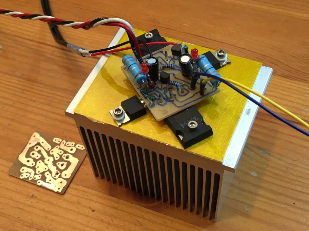
I am waiting for some LU1014's to arrive and decided to try an IRF610 in its place to see if I can get some music out.
This circuit is a real heater for a HA - about 30w rejected hot blooded class A heat for maybe a few hundred mW of audio power into head phones.
http://www.diyaudio.com/forums/head...lower-headphone-amplifier-13.html#post4893199
I am waiting for some LU1014's to arrive and decided to try an IRF610 in its place to see if I can get some music out.
This circuit is a real heater for a HA - about 30w rejected hot blooded class A heat for maybe a few hundred mW of audio power into head phones.
Last edited:
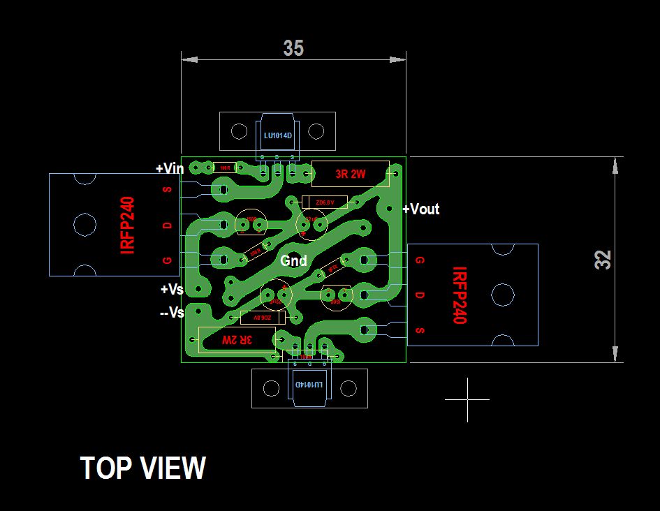
Nice 4 quadrant design ! Heat will be distributed more evenly this way.
BTW why do many people not cut excess lead wires of power transistors anymore ? I have learned long ago that excess wires are antennas and to keep them as short as possible but that might be outdated info ?!
BTW why do many people not cut excess lead wires of power transistors anymore ? I have learned long ago that excess wires are antennas and to keep them as short as possible but that might be outdated info ?!
Last edited:
JP,
I don't cut the leads for a couple reasons. Easy to use as probe points for testing, and let's me pull it out and re-use in another project if needed (as was done here). 🙂
A 10mm antenna stub is in the ten GHz freq range - hardly of concern here in audio.
I don't cut the leads for a couple reasons. Easy to use as probe points for testing, and let's me pull it out and re-use in another project if needed (as was done here). 🙂
A 10mm antenna stub is in the ten GHz freq range - hardly of concern here in audio.
OK, new to me probably because I never reuse parts and don't do "universal" stuff as you might know by now 😉 I do it the old fashioned way: making a design and revise it where necessary.
Don't underestimate the antenna working of excess lead wires. You might not hear RF but it can have its influence.
Don't underestimate the antenna working of excess lead wires. You might not hear RF but it can have its influence.
Last edited:
I agree that leads need to be kept short, and if longer then twisted pair, coax shielded etc. Most typical class AB amps in SS forum have a 100nF and 10R in series and a 1.2uH and 10R in parallel tied to the output node to keep the amp stable with reactive loads and also suppresses RF output well. I never see those on a Pass class A amp in this forum. I wonder why - would it be detrimental for class A operation or is it just purists trying to keep the audio path free of all filters?
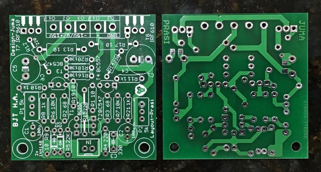

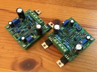
Using Hfe matched BC550C/BC560C's.
PCBs from Seeedstudio:
Built and awaiting testing:
nicely done X🙂, I think everything fits perfect😎...
what resistor combo are you using to set gain? R16/18/20 and R15.
just an info to other builders...R14 could be mounted below the board so that its very near to the G of IRF...
reg
Prasi
Last edited:
R16/R18 are 100R and R20 is 220R 0.5w
R15 is 220R per silk
Why mount that resistor underneath? To reduce parasitic distance?
Yes it fits all together perfectly. Nicely done on the layout! I like the 100nF SMT bypass cap pda on bottom. I use them always. It was nice to be able to fit a big fat 2200uF 16v rail smoothing cap on such a small amp.
I would have liked screw terminals on audio input but not a big deal.
Last edited:
yes, to reduce distances.Why mount that resistor underneath? To reduce parasitic distance?
I would have liked screw terminals on audio input but not a big deal.
i dont know why you prefer screw terminals for audio i/p😕, ease of cable connection? or you have them in plenty?. i think most people would prefer 2.54mm pitch jst connectors/ pcb headers , especially gold plated ones😉...
Yes, easy in/out from test setup. Most of my amps are like this so easy swapping in and out. For permanent use the plastic snap on header style (white plastic with detents) is good.
just observed from your build, there is a notch/groove to fit termi blocks together by sliding..
Attachments
Last edited:
just observed from your build, there is a notch/groove to fit termi blocks together by sliding..
Yes, I know - it would be the case if the two blocks were from the same manufacturer! 🙂 But as it turns out, they are not. 😛
- Home
- Amplifiers
- Pass Labs
- Juma's Head Amp