I agree it's not much sound but I think I can hear 2mV with my ears pressed to the cone. I am trying to make a silent amp, as in, you don't even know that it's on amp.
Really? Then build an F6... EXACTLY.. as per 6L6's guide.
Simple PS and All 🙄
DEAD silent... Ears pressed flat to the dust caps/ comp drivers of My tannoys.
Had to go back and check if the amp was actually plugged in.
Zero differences between on or off.
Seriously impressive.
Last edited:
Well I have built an M2 and Juma F5 with same specified PSU as F5/F6/M2 (33mF/4x0.47R parallel/33mF) per rail, and it's not quite dead silent. Maybe F6 has better PSRR?
2mVac of hum at the speaker is a lot.I agree it's not much sound but I think I can hear 2mV with my ears pressed to the cone. I am trying to make a silent amp, as in, you don't even know that it's on amp.
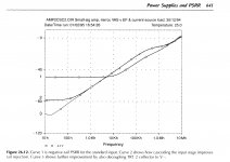
most of us would complain about 2mVac in a 25W amplifier since it is only -77dB ref maximum power.
But 1.6mVpp is ~0.56mVac and that is ~-88dB ref maximum power.
If the amplifier has a PSRR of 12dB for signal/interference below 200Hz, then the hum (0.14mVac) drops to ~-100dB ref maximum power.
Most listeners/Builders will tolerate 0.1mVac of Hum+Noise with normal sensitivity speakers.
D. Self's 6th edition shows PSRR measurements of "Blameless" (LTP -> VAS -> EFOPS) amplifiers. Neg rail PSRR is worse than pos rail PSRR; it ranges from -50dB to -80dB at 2xFmains frequency. For 1.6mV pkpk noise on neg rail, this becomes -113dB ref 25 Watts (if PSRR = -50dB), or else -128dB ref 25 Watts (if PSRR = -80dB). Notice that the trick behind curve #2 can be implemented in valve circuitry too.
_
_
Attachments
Hello,
is it a good idea to take yumas easy peasy capacitance multiplier to bring my 25 V (primary) transformers down to a supply voltage for an f5 amplifier, say around 30 V secundary ?
Any help is very welcome, because the other way might be to take an crc power supply with the required resistance (more expensive and takes more space).
With regards
Dirk
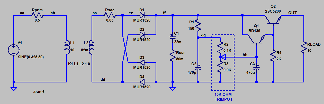
Yes, a capacitance multiplier is an acceptable method of powering a power amplifier. Do not copy post1.
You can use that missing resistor (R2,3), now shown in post36 by Mark to trim the output voltage of the multiplier.
The higher the Vdrop across the multiplier the hotter it will run. Be careful.
You can use that missing resistor (R2,3), now shown in post36 by Mark to trim the output voltage of the multiplier.
The higher the Vdrop across the multiplier the hotter it will run. Be careful.
Last edited:
The cap multiplier described here was designed for an F5 with small 2SK2013/2SJ313's. But if you give it a higher upstream voltage I don't see why it can't be used for the larger F5. The 25V primary will get you 35v DC rails. The cap multiplier can easily take it down 4v to 31v. I am not sure but it seems that a pot located where the 10k is allows adjustment of the voltage drop perhaps down to 25v. But 11v burned off is a lot of heat. You will need big heatsinks.
XR,
compare post1 to post36.
The 10k in post1 is not the missing resistor.
Post1 needs an extra resistor as shown in post36.
I described the multiplier operation in post34. Did you understand that?
Mark quickly added post35 showing the missing resistor that I referred to.
And then added post36.
compare post1 to post36.
The 10k in post1 is not the missing resistor.
Post1 needs an extra resistor as shown in post36.
I described the multiplier operation in post34. Did you understand that?
Mark quickly added post35 showing the missing resistor that I referred to.
And then added post36.
Last edited:
Thanks for straightening that out Andrew. Here is the correct diagram then. Reposted here for convenience. But in the context of using MOSFET device can we simply switch out the two BJT's for an IRFP?

Andrew and XR,
thanks for the realy fast answers.
So I go with the circuit of post 1, because 30V - 32V is the supply voltage I want to have.
Because of my transformer, I can only run a Iq of about 1A and I want to build the F5 version with 32V and 1A from the F5 turbo sheet.
What is that missing resistor, you refering ?
Dirk
By omitting the resistor at the capacitor your capacitor voltage ends up being one Vgs below supply rail.
It is very likely that the Vgs of the +ve side will be different from that on the -ve side. You will end up with different supply rail voltages.
You really need the extra resistor. This will enable you to trim the supply voltages so that they remain similar.
It is very likely that the Vgs of the +ve side will be different from that on the -ve side. You will end up with different supply rail voltages.
You really need the extra resistor. This will enable you to trim the supply voltages so that they remain similar.
Yes just swap out the two BJTs plus resistor R4 and replace with a single mosFET plus base stopper and protection Zener.Thanks for straightening that out Andrew. Here is the correct diagram then. Reposted here for convenience. But in the context of using MOSFET device can we simply switch out the two BJT's for an IRFP?
So, in the circuit of post 1, there are the resistors from plus and minus out to ground missing and they should be 2k, is that right?
Are there any other changes to make if I want to build the circuit of post 1 with my 25v transformer?
Thanks
Are there any other changes to make if I want to build the circuit of post 1 with my 25v transformer?
Thanks
No.
look at posts 35 & 36.
The capacitor between gate and zero volts needs a resistor across it.
The rail to gate resistor in series with the gate to zero resistor forms a resistive ladder.
You can adjust the output voltage (i.e. the volts drop across the mosFET) by adjusting the RATIO of these two resistors.
If the top one is 1k and the bottom one is 99k, then the voltage at the gate is 99% of the input voltage.
If the top resistor is set to 10k and the bottom resistor is 100k, then the gate voltage is 100/110 = 90.91% of the input voltage.
Both are when the output is supplying zero current.
As you draw current the voltage drops slightly from the quiescent state.
If you do as Mark has shown you can replace the 100k with a VR and adjust the output voltage while under load. Set it up so that the two rails are roughly equal.
Warning:
Do not use a 100k VR. It does not have sufficient current capability.
I would not recommend 10k either. ~7mA max current and <5mA for regular operation recommended.
Better with a 10k fixed resistor connected to Zero volts and then add on a 1k or 2k VR for the gate connection. 2k 500mW VR has a max current of ~16mA and a recommend regular current of <11mA. I prefer to operate at <50% of max current (=¼Pmax).
Last edited:
Thank you AndrewT. I think I've got it now.
A very nice circuit then, a capcitance multiplier with adjustable + and - output voltage. That should be of much interest for a lot of projects.
Greetings
Dirk
A very nice circuit then, a capcitance multiplier with adjustable + and - output voltage. That should be of much interest for a lot of projects.
Greetings
Dirk
It was the adoption of a mosFET take hid the disadvantage of the missing resistor.
Had a BJT been used the missing resistor usually shows up as a drop out glitch whenever ripple voltage exceeds 2times Vbe.
The Vgs of the mosFET is approximately 4times to 8times higher than Vbe and so the mosFET based multiplier can tolerate 4times to 8times the ripple voltage before drop out occurs.
One does not usually adopt an adjustable ratio for those resistors. One generally designs the fixed ratio to avoid drop out at the highest ripple one expects at the input. 95% to 98% usually gets one close enough. Mark's implementation adds a bit more flexibility for little cost.
I always recommend that ratio defining resistor. It's the traditional way to design a multiplier. You can set it very high, 98% to 99.9%, when that suits the duty, i.e. when using a mosFET dropper.
Member
Joined 2009
Paid Member
As an added wrinkle, Nelson had a MOSFET capacitance multiplier in one of the Zen amps I think, where the output was purposely modulated by the amplifier output signal so as to raise the rail voltage when the signal was larger.
This can be very useful for smaller current applications like preamps & DACs where you absolutely want as ripple free of a supply as possible. Smaller currents can probably use IRF610/9610. A 15VAC trafo with 2200uF caps and the multiplier gets some really nice performance and will drop the DC rail down to about 15V after losses in the multiplier. Won't be much heat output if not a lot of current being used. I suppose going with 18VAC trafo and then cap multiplier then followed by LM317 can give really good voltage regulated and low ripple design.
That's a nice performing chip. Are you saying we can skip the ripple eater completely?
I have never seen this one before so thanks for bringing it up here to our attention. Is there a negative output version as well?
I have never seen this one before so thanks for bringing it up here to our attention. Is there a negative output version as well?
- Home
- Amplifiers
- Power Supplies
- Juma's Easy-Peasy Capacitance Multiplier