In my simulations of an open-loop cascode design, the shown bandwidth extends to 1 MHz or more. If I were to control the bandwith with, for instance, a simple 1st order low-pass RC filter, would using such a filter at the input be the best option or do you advice otherwise and maybe a 2nd or higher order filter?
Please simulate all you want. I usually build real prototypes and test them. I would appreciate any simulations of my designs that anyone wants to share.
john curl: Please simulate all you want. I usually build real prototypes and test them. I would appreciate any simulations of my designs that anyone wants to share.
Simulating a design serves a specific purpose as most of us know. Of course the next step is building a prototype and test it.
Since we are discussing open loop desings in general I ask a question regarding a problem I run accross as a diy-er, which is; how can I best limit the bandwidth of an open-loop cascode design?
Frankly I do not see how we can share simulations of your designs we have never seen. The ones presented by us till now have been labeled as half-baked and second-guessing. Please correct me if I'm wrong.
courage said:In my simulations of an open-loop cascode design, the shown bandwidth extends to 1 MHz or more. If I were to control the bandwith with, for instance, a simple 1st order low-pass RC filter, would using such a filter at the input be the best option or do you advice otherwise and maybe a 2nd or higher order filter?
I think this is really your call. How much do you want to limit the bandwidth? From which freq do you want to roll off? The problem with input filters is that they do also influence input impedance, noise, etc, so the best thing is probably to make it as simple as possible; most people seem to be happy with 1st order roll-off.
If you can, a lpf at the output would have the benefit that it also attenuates preamp-generated noise, so possibly a combination of input and output lpf would be optimal. But again, without knowing your specific circuit, I can give only general hints.
Jan Didden
You are correct courage. Nobody but me has my exact design, but I would be interested in simulations of similar designs. I don't know why or how I would best approach limiting the bandwidth of a folded cascode. Hanging a cap on the output would do a good job.
john curl said:Please simulate all you want. I usually build real prototypes and test them. I would appreciate any simulations of my designs that anyone wants to share.
Well - does this fit?
Attachments
John Curl: I don't know why or how I would best approach limiting the bandwidth of a folded cascode.
Am I correct to conclude that with your open-loop folded cascode design it was not necessary to limit the bandwith as such?
John Curl: Hanging a cap on the output would do a good job.
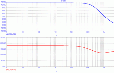
I assume an R-C-R configuration would do the job, but to what extend does it effect the output impedance? Looking at the simulation plots PMA (thanks Pavel) presented, what approach is best in limiting
the bandwidth to say 90 kHz?
Janneman, thanks for your input and any comment on given plots and suggested roll-off @ 90 kHz.
Tansconductance preamp simulations.
(Actually I am in Spain and it’s not always easy to find Internet places.)
More If I can later.
(Actually I am in Spain and it’s not always easy to find Internet places.)
More If I can later.
An externally hosted image should be here but it was not working when we last tested it.
An externally hosted image should be here but it was not working when we last tested it.
An externally hosted image should be here but it was not working when we last tested it.
An externally hosted image should be here but it was not working when we last tested it.
I'm surprised, your output sinwave looks very good without source resistors. What jfet spice models do you use?
Sorry, but I have to ask. The schematic looks OK, but what can I learn from this simulation? Bandwidth? That takes about 5 min with an audio analyser on a real preamp. It changes with volume pot position. DUH!
What about noise injection from the second stage to the input? What about distortion with output and frequency?
What about noise injection from the second stage to the input? What about distortion with output and frequency?
Here the fets spice models I use for sims:
.MODEL 2SK170-BL NJF (VTO=-0.498451 BETA=0.0500021 LAMBDA=2E-9 RD=3.85
+ RS=5.17045 IS=3.95F PB=1 FC=.5 CGS=85.4P CGD=22.7P)
* Toshiba 40 Volt 20mA 35.3 ohm Dep-Mode N-Channel J-FET 08/10/02
**********
.MODEL 2SJ74-BL PJF (VTO=-0.498451 BETA=0.0500021 LAMBDA=5E-10 RD=4.95
+ RS=5.17045 IS=6.32F PB=1 FC=.5 CGS=52P CGD=115P)
* Toshiba 25 Volt 20 mA 35.3 ohm Dep-Mode P-Channel J-FET 08/10/02
*SRC=2SJ76;QSJ76;MOSFETs P;Gen. Purpose;140V 500mA
.MODEL 2SJ76 PMOS (VTO=-1.5 KP=122M GAMMA=18.6
+ PHI=.75 LAMBDA=1.48M RD=.84 RS=.84 IS=250F PB=.8 MJ=.46
+ CBD=444P CBS=533P CGSO=384N CGDO=320N CGBO=346N)
* -- Assumes default L=100U W=100U --
* 140 Volt .5 Amp 6 ohm Enh-Mode P-Channel MOSFET 07-28-1995
* 2SJ76, 1993 JAPANESE FET MANUAL, P.16
**********
*SRC=2SK216;QSK216;MOSFETs N;Gen. Purpose;200V 500mA
.MODEL 2SK216 NMOS (VTO=1.5 KP=80M GAMMA=18.6
+ PHI=.75 LAMBDA=521U RD=.84 RS=.84 IS=250F PB=.8 MJ=.46
+ CBD=658P CBS=790P CGSO=26.4N CGDO=22N CGBO=852N)
* -- Assumes default L=100U W=100U --
* 200 Volt .5 Amp 6 ohm Enh-Mode N-Channel MOSFET 07-28-1995
* 2SK216, 1993 JAPANESE FET MANUAL, P.38
**********
Now what would be interesting Mr Curl is that you enlighten us a little more on this:
Thanks 😉
john curl said:What about noise injection from the second stage to the input? What about distortion with output and frequency?
Thanks 😉
john curl said:PMA's simulation looks good. It looks just like what I measure. Same amount too. Good work.
Thank you, John. Appreciated.
Regarding simulations
Friends,
I have received several questions concerning simulation today. The problem is not in circuit diagrams or spice models, IMO. For circuits like this, simulation usually yields reliable results. The problem is in application of simulation software for distortion spectral analysis - think about it.
I would like to mention several points:
1. I do not intend to build, try to copy, or to be guessing (this word has become popular recently) its real circuitry. I was just curious how simulation fits to measurements on real circuit and I got the answer.
2. I do not intend to support or consult attempts to simulate the preamplifier. The proper use of simulation tools is a part of my know-how, like the circuit design is a know-how of John Curl.
3. The circuit was designed by John Curl and I fully respect this fact. I congratulate him to smart circuit idea.
Yours,
Pavel Macura
Hi Pavel,
I don't think any of us who have dealt with you would think you would try to reverse engineer John's products. A sim doesn't tell you what happens when you build something either. It only gives you an idea as long as your construction is up to par. That and in a perfect world. 😉
I congratulate you on being able to simulate a circuit so well, and doing it for the other members here.
-Chris
- Status
- Not open for further replies.
- Home
- Amplifiers
- Solid State
- John Curl's Blowtorch preamplifier