john curl said:You don't fully qualify yet, but keep at it and I will make an exception.
Please do
 You already know the taste of your own medicine
 dimitri said:better not to load this output stage with a current source at all
My experience also but that's only based on a listening test. 😀
andy_c said:Here's the LTspice sim that gave the data.
Thanks Andy/jcx for this detailed model. 🙂
Your Cn loop gain result looks reasonable.
syn08 said:
This is an interesting question per se; how do you mathematically identify feedback? That is, given a complex function that defines a linear and time invariant causal system how do you decide it originates from a "feedback circuit", e.g. a A/(1+A*B) form can be derived (or any other criteria that defines "feedback circuit"?).
I've said it before - to me, feedback is more like an analysis instrument rather that a circuit topology.
I look at this in a very simple way. When you are driving your car does FB exist? How do you know?
traderbam said:Thanks Andy/jcx for this detailed model. 🙂
Your Cn loop gain result looks reasonable.
jcx did the real work. I just did a slight mod of his simulation.
BTW, there's a much more detailed schematic of the AD797 in Scott's AES preprint. For more info on this, feel free to shoot me an email.
There is bootstrapped cascoding of the input stage, bootstrapping of the EFs that buffer the high-impedance node - the works. Scott pretty much thought of everything.
In my diagram, I calculate that the transfer function is:scott wurcer said:So there is a semantic element to this. I didn't double check but I assume your drawing yields that the ouput voltage is gm*Rl independent of A (certainly for .8 < A < 1). That was the point.
Vout/Vin = gm/ [ 1/A ( 1/Zc - 1/Zn ) + 1/Zn ]
If you substitute Zc = 1/sCc and Zn = 1/sCn this equals the equation in the AD797 datasheet except for the sign. Indeed the output is independent of A when Zn=Zc. As I see it this is because the transimpedance becomes infinite and therefore the NFB becomes infinite. "A" is not the whole forward gain - because this is a transimpedance circuit, not a voltage gain circuit. Andyc remarked on this.
The cat got it.As I said I did run this circuit with both current mirror pins brought out. It was a long time ago but I remember with an input gm of 1/100 Ohms or so and 10K resistors instead of compensation caps (just like Dimitri's drawing) I could run the circuit at an open-loop gain of 100. The output stage non-linearity was nulled even at Rl =100 Ohms. I found the empty box in my stuff last night so the parts are gone.
 Sure, but I do not believe that the output error was eliminated, but reduced more and more as f reduces. The null - or error minima - represents a maximum low f loop gain. The correction is necessarily band-limited.
The day the whole world converts to metric will represent a landmark in human evolution. Imperial is an unnecessary pest promoted by the sort of neurotic people who care more about the size of the glass than the taste of the beer. 🙂BTW when we buy your fancy European dishwashers we have to contend with English to metric mismatch. I had one plumber come and cut everything off and then say ef-it you figure it out and leave unpaid.
Attachments
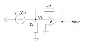
The loop gain through Zn is derived as follows.
Cut the link between Vout and Zn. Feed Zn with V'. Calculate the transfer function Vout/V' with Vin=0. Assume output Z of buffer A = 0.
Summing currents into Ve node: -(V'-Ve)/Zn = Ve/Zc.
Solve for Ve/V' = -Zc/(Zn - Zc)
Substitute Ve = Vout/A, Vout/V' = -A.Zc/(Zn - Zc)
If we assume Zn and Zc are capacitances,
loop gain = -A.Cn/(Cc - Cn)
andy_c said:
jcx did the real work. I just did a slight mod of his simulation.
BTW, there's a much more detailed schematic of the AD797 in Scott's AES preprint. For more info on this, feel free to shoot me an email.
There is bootstrapped cascoding of the input stage, bootstrapping of the EFs that buffer the high-impedance node - the works. Scott pretty much thought of everything.
This is the reason it is not universally useful, these things eat up headroom and this circuit is far from rail to rail which is required these days. Never tried "Muntzing" it.
BTW that is the real schematic, there are no hidden surprises AFAIK except the offset null scheme might be different in reality (very lame HP plotter schematic).
traderbam said:
Sure, but I do not believe that the output error was eliminated, but reduced more and more as f reduces. The null - or error minima - represents a maximum low f loop gain. The correction is necessarily band-limited.
Yes you are right of course it fails at the unity gain BW and improves as 1/omega**2 rather than 1/omega. To see intuitively think of the vector magnitude error of a large signal with a small quadrature signal subtracted. It was a very useful improvement at <100kHz and the patent ended up mostly a vanity thing I guess (it runs out in Nov.).
scott wurcer said:Never tried "Muntzing" it.
LOL! "There's something about a Muntz TeeVee..."
Andre Visser said:
My experience also but that's only based on a listening test. 😀
Do somebody need an experiment to know that it is bad to touch 120V phase by naked fingers standing on a wet floor? 😀
syn08 said:
I am sure everybody will appreciate an example (graphic, citation, link, whatever, except for empty descriptive words) that illustrates "non-harmonic, but signal correlated distortion".
Some of them, like PSU intermodulation skirts, jitter and DAC spuriae SFDR are known even to pure objectivists. The other are not easy to find by steady-state harmonic analysis with emphasized periodicity and averaged non-periodicity.
I think that is the real problem, PMA. Continually fishing for the lowest measured distortion with a test tone or two, just seems to run out of steam, especially when feedback is used to create the low distortion, in the first place. I suspect it is fm, aliasing artifacts, jitter, and maybe a number of other factors that are most important.
It just would not make any sense otherwise, unless all golden ears are crazy and foolish. I know that many here would like to believe that, as it would ease their insecurities, but it just doesn't follow with experience that everything is imaginary.
Dr. Lipshitz would like you to think so, and he certainly doesn't believe anything I have ever had to say on the subject. However, what is the point then, of pursuing audio, if you can't hear the difference?
In the end, I just have to trust my ears, and TRY to correlate what I hear with whatever measurements I can make, and trust myself for the rest. Works for me.
john curl said:I think that is the real problem, PMA. Continually fishing for the lowest measured distortion with a test tone or two, just seems to run out of steam, especially when feedback is used to create the low distortion, in the first place. I suspect it is fm, aliasing artifacts, jitter, and maybe a number of other factors that are most important.
It just would not make any sense otherwise, unless all golden ears are crazy and foolish. I know that many here would like to believe that, as it would ease their insecurities, but it just doesn't follow with experience that everything is imaginary.
Dr. Lipshitz would like you to think so, and he certainly doesn't believe anything I have ever had to say on the subject. However, what is the point then, of pursuing audio, if you can't hear the difference?
In the end, I just have to trust my ears, and TRY to correlate what I hear with whatever measurements I can make, and trust myself for the rest. Works for me.
Hear hear. Always trust your ears! 🙂
I used to follow a similar design process - listen, iterate the circuit, listen again, measure something, etc. This worked up to a point for me but I found I kept getting stuck on intermediate plateaus with a handful of design rules of thumb that were more or less loosely correlated to sound quality. I don't do this anymore.
traderbam said:
Hear hear. Always trust your ears! 🙂
I used to follow a similar design process - listen, iterate the circuit, listen again, measure something, etc. This worked up to a point for me but I found I kept getting stuck on intermediate plateaus with a handful of design rules of thumb that were more or less loosely correlated to sound quality. I don't do this anymore.
Hello Traderbam
So how to you design, do you have a technical goal , and how do you improve your design.
What reference speaker do you use for evaluation.
Regards
Arthur
PMA said:Some of them, like PSU intermodulation skirts, jitter and DAC spuriae SFDR are known even to pure objectivists. The other are not easy to find by steady-state harmonic analysis with emphasized periodicity and averaged non-periodicity.
Ok, trying to be patient here 😀
In DACs, Spurious-Free Dynamic Range (SFDR) is the ratio of the RMS amplitude of the carrier frequency to the RMS value of their next largest distortion component.
Now, please try to explain to an objectivist how is this a "non-harmonic, but signal correlated distortion". Include in the explanation how any kind of intermodulation distortion (including "PSU intemodulation", whatever that is) can be non-harmonic. I'm not asking about (nondeterministic) jitter, 'cause that's affecting the noise floor and is therefore out of topic.
john curl said:
<snip>
It just would not make any sense otherwise, unless all golden ears are crazy and foolish. I know that many here would like to believe that, as it would ease their insecurities, but it just doesn't follow with experience that everything is imaginary.
Dr. Lipshitz would like you to think so, and he certainly doesn't believe anything I have ever had to say on the subject. However, what is the point then, of pursuing audio, if you can't hear the difference?
In the end, I just have to trust my ears, and TRY to correlate what I hear with whatever measurements I can make, and trust myself for the rest. Works for me.
And the corollary, if it's not there, then Muntz it. You certainly need to make a difference to survive. It's understandable.
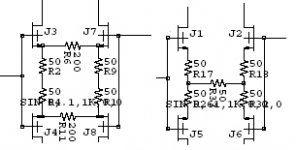
OK, on to a practical problem. Since most of us are stuck with 2SK170/2SJ74 pairs for complimentary design I had a question about adjusting for residual evens due to inevitable mismatch. The two circuits in my picture have identical noise, gm, and small signal transfer function (distortion with ideal matched compliments). The circuit on the left however allows easy trim (by adjusting R6/R11) for seconds with minimal offset voltage implications.
I’m not showing the rest of the circuit for now but sims give me a tolerance of +-10% on Idss match for very little performance degradation as long as one is willing to do two interactive trims.
BTW the "rest of the circuit" uses all four currents equally so the input is used in a completely complimentary fashion.
Attachments
- Status
- Not open for further replies.
- Home
- Amplifiers
- Solid State
- John Curl's Blowtorch preamplifier