John:
Scott has not been forthcoming with the specifics you asked for. That is his prerogative. However you can try the experiment of loading the output yourself (a current source is not much to breadboard and test) and it may not help.
The nearest similar part to the AD797 is the LT1115 from Linear Technology. Looking at the datasheet three differences are obvious, first the distortion is higher, second the LT1115 has input bias compensation, which doesn't seem to be in the AD797 (input bias compensation can be a source of noise and errors) and, most relevant, the applications refer to using a 2 mA current source to the negative rail to reduce the output distortion. I don't think the LT1115 (or its higher spec cousin) will have the same HF performance since they are a more conventional design but they may be a viable alternative at least in the distortion analyzer. At least they admit that the output section can be more linear when biased into class A.
However the AD797 has transistors that are pretty good compliments so biasing to the negative rail may not be optimum.
1audio said:The nearest similar part to the AD797 is the LT1115 from Linear Technology.
If I remember well, the LT1115 was supposed to be a simplified version of the LT1028, which I don't know if it's made anymore.
1audio said:second the LT1115 has input bias compensation, which doesn't seem to be in the AD797
AD797 has it as well (Scott Wurcer would correct me if I was wrong). BUT - the AD797 has the output stage trick (neutralization) that 1028(1115) has not.
797 'sounds' better.
Well, it looks like I scared off Scott Wurcer, speaking my mind. I regret this and I hope that Scott will contribute more input on his AD797, as he implied that he was going to. I realize that it is neutralization related info, and not open loop linearity, but everything can be useful when making test equipment, for certain.
Well, it looks like I scared off Scott Wurcer, speaking my mind. I regret this and I hope that Scott will contribute more input on his AD797, as he implied that he was going to. I realize that it is neutralization related info, and not open loop linearity, but everything can be useful when making test equipment, for certain.
With 600 Ohm load and G=10 AD797 has THD<1ppm for the frequncies <12...15kHz (Fig.45). Do you need less, John?
scott wurcer said:
Let's get Bob Cordell involved! I'm up there once a year or so.
bear said:Up? Up where?
Albany is out or over from you... due west.
Where is Bob Cordell?
Ur in Cambridge? I'll be in Boston, I think on May4th... but perhaps this is best off thread?
Maybe this is the kernel of something...
_-_-bear
I'm in Connecticut, not exactly sure what you have in mind, a burning amp meet in the North East?
Pete B.
Let me clarify my needs: I have 2 separate circuits that I have to optimize.
One circuit has a gain of about 30, and is used to amplify phono MC cartridges.
The other MIGHT have a gain of about 30, but is used as the front end of my ST 1700B analyzer.
One is for listening, the other is for measuring.
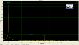
Measuring is always a challenge, and I want to get to below -130, if possible, with 7th harmonic being the MOST important harmonic that I don't want to see on the screen. I, now, have some 7th harmonic on the screen. How can I reduce this? Is it the fault of the AD797 or is it some other IC or component in the circuit?
The other need is for best sound. Measurement is OK for such a circuit, but open loop linearity is suspect. This is more important to me than closed loop measurement, especially with the nasty pulse like signals that this stage is subjected to from the MC cartridges. I have measured them and published the results, so I know the mine field that I am walking in. I also make open loop designs that accomplish this task with flair, but they are too expensive and exotic to be used in a commercial product, such as the phono stage that Parasound wants to make.
I must use whatever IC that I get in the most optimum way, and this requires both inside knowledge of the design, and experience with the IC, even before the product is subject to subjective evaluation.
Not so easy, is it?
One circuit has a gain of about 30, and is used to amplify phono MC cartridges.
The other MIGHT have a gain of about 30, but is used as the front end of my ST 1700B analyzer.
One is for listening, the other is for measuring.
Measuring is always a challenge, and I want to get to below -130, if possible, with 7th harmonic being the MOST important harmonic that I don't want to see on the screen. I, now, have some 7th harmonic on the screen. How can I reduce this? Is it the fault of the AD797 or is it some other IC or component in the circuit?
The other need is for best sound. Measurement is OK for such a circuit, but open loop linearity is suspect. This is more important to me than closed loop measurement, especially with the nasty pulse like signals that this stage is subjected to from the MC cartridges. I have measured them and published the results, so I know the mine field that I am walking in. I also make open loop designs that accomplish this task with flair, but they are too expensive and exotic to be used in a commercial product, such as the phono stage that Parasound wants to make.
I must use whatever IC that I get in the most optimum way, and this requires both inside knowledge of the design, and experience with the IC, even before the product is subject to subjective evaluation.
Not so easy, is it?
I agree with almost everything you are saying about importance for good sound.
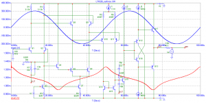
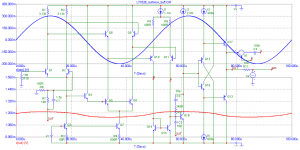
The measured 7th content is confusing for me, however. My associate is able to measure my discrete preamp like this, using soundcard with opamps, and external audio generator (AP)
The measured 7th content is confusing for me, however. My associate is able to measure my discrete preamp like this, using soundcard with opamps, and external audio generator (AP)
Attachments
john curl said:Yes, IF I want to use it for measurement.
John,
I certainly doubt you could get less than that, from AD797 or any other IC. But then if you can write down a set of key parameter for this amp (bandwidth, distortions, IMD, slew rate, noise, input bias, offset, etc...) I'm sure someone could help with either an IC or hybrid solution. Also some details regarding your application may also lead to a few suggestions.
Traderbam,
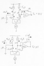
I think I have a picture that explains the operation of the circuit. Taking a step back let’s just look at a DC case to show how the current mode cancellation works. I admit my use of the term neutralization might be unfortunate because it has a specific meaning in the RF world. In both cases we have a floating current mirror circuit trying to make 10V out with a load of 1M on the current mirror to ground. The input gm represented by the two current sources on top has to supply 10uA (differentially) to make 10V across the 1M load. The output buffer is in the first case a perfect G = 1 follower. In the first case the second 1M does nothing because the voltage across the buffer is always identically 0. In the second case let the buffer be G = .9, a fixed 10% error (in fact the input to output transfer function could be non-linear). I hope it’s clear that the output buffer supplies the current that is mirrored so that the input stage still needs exactly the same +-5uA to make 10V at the output i.e. the voltage transfer function of the output stage has no net error back at the input gm so that the global feedback does not see it. Please forgive that I rounded 1 1/9 to 1.1. Yes, if you want to consider a current mirror as a feedback circuit then you could argue such. These arguments like, “an emitter follower is feedback”, don’t send circuit design, as an art, forward. Extension to where the 1M resistors are replaced by the compensation capacitance should now be obvious. In this case the correction is only for AC signals which is OK since the DC gain is >5*10e6 anyway.
John - This IS a linearization of the open-loop transfer function.
Stinius – No the capacitance is the compensation capacitance parasitics are cancelled by symmetry
Wavebourn – I hope this explanation is OK.
Attachments
Scott, I think a classical functional drawing with couple of integrators would look more understandable in this case.
PMA said:Slightly off topic - whom can I meet in Munich 2009 HighEnd, on May 21?
Hi-end or AES?
Jan Didden
You can use two of them, first with gain of 6, then 5I want to get to below -130,
As you cannot modify input stage you might consider ad844 with external output stage, connected to TZThe other need is for best sound.
- Status
- Not open for further replies.
- Home
- Amplifiers
- Solid State
- John Curl's Blowtorch preamplifier