I suggest to those who want to know and understand why we use tubes and fets, study the effect of 7th harmonic (and its related IM products) in music.
You can do this by Googling: 7th harmonic music.
Check it out, and then you too, can know something that I know, already.
You can do this by Googling: 7th harmonic music.
Check it out, and then you too, can know something that I know, already.
You mean this: ?
I knew this for a while , thats why when I was "advised"
to not go the route of complimentary input stages (leach, etc)
for this reason , I listened.
Not just to take any advice , I built a leach../ tried it on full
range and sub use. For sub use I liked it (triples rule for
LF) , but for detail , a bit of sourness was evident. 🙁
Spice's FFT showed me why , even as H7 was low , it WAS
there.I'm listening to an APT1 clone now and think I
will stick with it for listening purposes. (no 7 at all) 🙂
OS
It's as if our ears had a built in programming allowing us to hear - if we listen very carefully that is - that the seventh was fundamentally different from other harmonics. It sounds "sour" whereas other basic fractions, intervals, sound "sweet." In more precise musical terminology, the seventh sounds "dissonant," whereas the others sound "consonant." Most musicians with good theoretical training, or a very good ear, have long known about the phenomena of the seventh harmonic. A few physicists studying acoustics also know about the anomaly. But it was just considered one of those many quirks of nature with no special meaning. Arnold Keyserling appears to be the first in modern times to realize the significance of this acoustic phenomenon.
I knew this for a while , thats why when I was "advised"
to not go the route of complimentary input stages (leach, etc)
for this reason , I listened.
Not just to take any advice , I built a leach../ tried it on full
range and sub use. For sub use I liked it (triples rule for
LF) , but for detail , a bit of sourness was evident. 🙁
Spice's FFT showed me why , even as H7 was low , it WAS
there.I'm listening to an APT1 clone now and think I
will stick with it for listening purposes. (no 7 at all) 🙂
OS
Doesn't the Leach power amp use bipolar transistors in the complementary input stage? Not optimum, compared to fets.
Yes , it does. I have never built an FET "clone" but I have simulated a cascoded variant with fets. The 7th was even lowerDoesn't the Leach power amp use bipolar transistors in the complementary input stage
but STILL there.
This is why mr. cordells hypothesis about "fighting" rings true.
I tried GK's "unbalanced Cdom" experiment on both
topologies.
The total THD in both the apt and fet leach stayed constant
but the harmonics of the thd changed in proportion to
the imbalance.
The leach's 7th increases with the mismatch but
I could not get the APT to change at all (In fact almost no
h7 at all).It is not the devices , but inherant to the topology
.. this does not seem to hold true for class A ... as the
genesis stealth amp I have is fully complimentary but
sounds soooo sweet.
(I like fet's, too , next amp will be a cascoded fet LPT , but
single ended.)
OS
With bipolars, and enough emitter degeneration, we get more linear compl. diff. input stage, than with JFETs, in real world. The case is that NPN/PNP matching in real BJT devices is MUCH better and easier, than with JFETs and MOSFETs. Also, the subjective listening comparison does not show any advantage of JFET comp. diff. input stage, compared to emitter degenerated BJT.
Mr. Leach forgot to apply one very important distortion cancellation mechanism in his input/VAS, so his distortion is higher.
Mr. Leach forgot to apply one very important distortion cancellation mechanism in his input/VAS, so his distortion is higher.
Mr. Leach forgot to apply one very important distortion cancellation mechanism in his input/VAS, so his distortion is higher.
what ? (mechanism) I have the simulation up and running.. 😀
OS
which leach..?Just a hint, please review the VAS.
the first (circa 1976) has no Cdom and shunts.
the second (2.1, I think.. has Cdom and active sourcing -4 devices)
and the "super leach" has a 6 device VAS with nested FB !
OS
Whatever approach we chose, I think that 7th harmonic is the most important distortion to reduce to virtually unmeasurable, if possible.
A strictly differential fet pair should be more linear than a bipolar pair, but there should be an advantage in the H bridge configuration as it does not allow the S curve to bend over, as the complement takes over to supply the current path. This should reduce higher order odd distortion at higher modulation levels.
Source or emitter degeneration is problematic, in my opinion, if only for the added input noise. However, I know that PMA has done an excellent job with his input stage, even though I would not elect to do it that way.
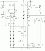
We are driving loudspeakers , not motors.. 😀advantage in the H bridge configuration
Talking about strange topologies , some amps use the
comp. differentials to drive the OPS directly (with no H7 at
all) This strange amp also sounds better than any I have
heard.. (attached)
OS
Attachments

ostripper said:You mean this: ?
I knew this for a while , thats why when I was "advised"
to not go the route of complimentary input stages (leach, etc)
for this reason , I listened.
Not just to take any advice , I built a leach../ tried it on full
range and sub use. For sub use I liked it (triples rule for
LF) , but for detail , a bit of sourness was evident. 🙁
Spice's FFT showed me why , even as H7 was low , it WAS
there.I'm listening to an APT1 clone now and think I
will stick with it for listening purposes. (no 7 at all) 🙂
OS
Well following that advice you should also steer clear of the APT1 because, electrically the input stage and VAS is just as symmetrical from input-to-output as is the Leach. It is also every bit as susceptible to the common mode “Miller cap fight”.
If anything, the APT method (borrowed from the ancient OTA op-amp topology) of mirroring the current in one leg of the LTP to provide a drive signal to the complementary VAS transistor is inferior (for a few reasons) to using a complementary LTP instead.
But then again I guess we can all just base our subjective conclusions on a misunderstanding of how these circuits actually work 🙄
By GK - (for several reasons)
What are they?, maybe just the biggest ones for those of us
with less understanding..
OS
Edit- I noticed it went from "several" to "few" , all I want
is to get it to "none" or "insignificant" , and
maybe increase the "understanding"
I don't think that you understood my input, ostripper. I was referring only to input stages.
VAS fighting
Hi Glen,
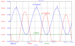
You are right, hardly any VAS fighting IF if the gain is considerably reduced (i.e. crippled) by terminating the inputs (of the VASes) with a low impedance (1k). However, this is what Bob said (bold font by me):
"The effect may be worse when the VAS is very un-crippled, with a very high impednace at its input (VAS transistors with emitter followers in front of them, stabilized helpered current mirrored loads top and bottom of the input LTPs)."
See below how devastating it can be.
Cheers,
Edmond.
edit: dumb question, what's that APT1 thingie? Does somebody have a link to the schematic?
G.Kleinschmidt said:I have to admit to being confused now because your experimental results have resulted in rather different conclusions to mine.
As far as the VAS common mode current that flows in a fully symmetrical design goes, as far as I can see, the value imbalance between the Miller compensation capacitors is a relatively minor issue (in some cases).
To illustrate the point I’ve attached a screen shot of a basic sim to this post.
The red trace is the output voltage (at 20kHz) and the green and blue traces are the PNP and NPN VAS transistor emitter currents respectively.
The VAS idle current is 10mA and there is about double the AC voltage swing in one VAS transistor than the other due to one Miller cap being 100pF and the other 150pF.
This is a significant imbalance, still, however neither VAS transistor comes close to being cut off.
[snip]
Cheers,
Glen
Hi Glen,
You are right, hardly any VAS fighting IF if the gain is considerably reduced (i.e. crippled) by terminating the inputs (of the VASes) with a low impedance (1k). However, this is what Bob said (bold font by me):
"The effect may be worse when the VAS is very un-crippled, with a very high impednace at its input (VAS transistors with emitter followers in front of them, stabilized helpered current mirrored loads top and bottom of the input LTPs)."
See below how devastating it can be.
Cheers,
Edmond.
edit: dumb question, what's that APT1 thingie? Does somebody have a link to the schematic?
Attachments
'There's no free lunch here' and no ideal topology - 'just sensible tradeoffs' - to quote a well known source.
Someone commented on the forum that th e best result s are from designers that settle on a good topology (and there are many, some admitedly a bit better than others) and then refine their circuit and work successfully around the shortcomings.
For me, its fully complimentary input to output. I am comfortable with bipolars throughout so thats what I'v e stuck to. (But for phono amp inputs, its JFET . . . . if I can get those damn things from my friends at Linear Systems. Help me out there Paul!).
I'll take my chances with the fighting VAS Cdoms over Doug selfs single ended approach any day.
Edmond, I don't know that I would buffer an LTP current mirror load towards the VAS (if I understand your description correctly). Seems to me to be a recipe for a whole lot of other problems.
VAS fighting
Hi Bonsai,
I'm not sure if I understand you correctly, but I think your question is how to stabilize the VAS current and at the same time maintain a high impedance at the VAS inputs, right?
Cheers,
Edmond.
Hi Bonsai,
I'm not sure if I understand you correctly, but I think your question is how to stabilize the VAS current and at the same time maintain a high impedance at the VAS inputs, right?
Cheers,
Edmond.
- Status
- Not open for further replies.
- Home
- Amplifiers
- Solid State
- John Curl's Blowtorch preamplifier