I spoke with him on one of exhibitions, probably 20 years ago, when his family name was Shushurin
32W into 8 ohms with <3% THD and <10% IMD 5V/us slew rate 3.1 ohms output Z 2.74A peak output current
IMO, every music lover who is designing hifi for the obsessive pursuit of sound quality really needs to free their imaginations from the shackles of conventional specs.
The best is, that the dipping in impedance comes from the constant pursuit to provide speakers with a linear frequency/phase response and a certain sensitivity (at a given amplifier reference output impedance), but this exactly leads just into the opposite if you use this amplifier:
The more the speaker designer wanted to equalize the frequency/phase response, the more likely there are impedance variations, but the deeper these dips are, the more non linear are frequency and phase response.


So why using a speaker against the intentions of the designer with such an mislead amplifier design ?
Are audiophiles better in electro acoustics than speaker designers ?
Are any of the accomplishments of audio engineering (of the last 60 years) now obsolete ? Are good products the ones, which are accepted (not necessarily bought) by a large crowd of dumb mislead sheep ?
You 'subjective' guys really give me the rest.
reinhard said:No, he was in TV Sets,
Strictly speaking, he was in "Radio" magazine. 😀
There was an institute in Lvov, where they had access to Western and Japanese gear and publications, and their goal was to repeat something similar, but using Soviet "civil" parts. However, there were better parts manufactured for military, but they were made of unobtainium for designers of audio gear, though Shushurin's publications specified new "civil" parts often unknown yet for the general public.
Jon Lord said:
The more the speaker designer wanted to equalize the frequency/phase response, the more likely there are impedance variations, but the deeper these dips are, the more non linear are frequency and phase response.
...except when mechanical resonances were minimized mechanically.
...except when mechanical resonances were minimized mechanically.
Just like in the following one ...
WATT/Puppy
I only have a problem with using an amp with a DF of 2 on it.
Yes, the "1" was much worse, but this says to me that even recent, mature speaker designs from a very skilled speaker designer don't allow the use of such an amplifier.
I would say 99.999 % of all speakers and 100% of all good speakers would produce +-2dB variations on this LAMM amplifier.
This would be just like using 20% toleranced parts in a $130000 RIAA stage, isn't it ?
Would you accept this ? ... 😉
Interesting ideas.
I was convinced that an audio system was something to be enjoyed. If it takes a special room where only one person can enjoy it, it falls short for me. The view from a family guy. At least the surround system is in another room for me.
True, there is always a "sweet spot" where what you hear is the best, but the sound outside of this area shouldn't degrade quickly as you leave that area. The sound should be enjoyable as you move around.
A thought on the Watt designs. Why would someone design a hard to drive speaker? If the amplifier can not perform at it's best, doesn't that degrade the performance of the entire system? To my way of thinking, if you were to design a speaker with reasonable and expected impedance (including the phase term), wouldn't that tend to sound better on most systems? An amplifier busting a gut trying to drive a loudspeaker isn't a nice thing to hear, and there are plenty of really good amplifiers out there not designed to run silly loads. It seems to me that this would be a (gross) error on the designer's part. I feel the same way about any speaker brand that is a "difficult load".
-Chris
john curl said:So what? Apparently, frequency response in ONE position is not that important.
Except in this case it's ALL positions.
By the way, a friend of mentioned here Shushurin, his name is Konstantin Baklaev, still works on speakers with flat light membranes, so both amps and listeners would be happy.
Bob Cordell said:It is notable that John's JC-1 DOES NOT use the usual pair of Miller capacitors back to the VAS inputs, and so appears not to be subject to this problem.
I showed ages ago in another thread that the CM currents due to gm / Miller cap value imbalance need to be pretty large for the overall linearity of a typical amplifier to be significantly degraded (even for a class A TMC amp with ~0.001% THD-20).
The JC-1 has seems to have a such a non-linear MOSFET VAS anyway (the amplifiers rather high low-order harmonic spectra shows that the output stage distortion is not dominant) that even if it did have the conventional Miller compensation, I doubdt that even 10% capacitance value imbalance would make a jot of difference.
john curl said:Bob Cordell in the past and just now has made one of the most significant criticisms of complementary design that I have seen contributed here.
Hi John,
I'm not sure how to read this. Is this a compliment on my post?
BTW, I would never criticise the use of a complementary VAS. I just think that the unipolar way of driving the complementary VAS is just as good, if not better than, the use of complementary differential pair inputs. Each approach has its pros and cons.
Sorry for the delayed response. I am now up in Montreal at the FSI show.
Cheers,
Bob
G.Kleinschmidt said:
I showed ages ago in another thread that the CM currents due to gm / Miller cap value imbalance need to be pretty large for the overall linearity of a typical amplifier to be significantly degraded (even for a class A TMC amp with ~0.001% THD-20).
The JC-1 has seems to have a such a non-linear MOSFET VAS anyway (the amplifiers rather high low-order harmonic spectra shows that the output stage distortion is not dominant) that even if it did have the conventional Miller compensation, I doubdt that even 10% capacitance value imbalance would make a jot of difference.
Hi Glenn,
I don't recall your particular simulation, but I have done simulations of a complementary bipolar input pair architecture that actually showed the VAS transistors going into cutoff under some conditions due to fighting. This may not always be the case with every design, but I was surprised how bad the effect was if I looked at the actual current flowing in the VAS transistor, rather than just looking at the output of the amplifier.
This was at 20 Khz, near full power. The VAS signal currents were fairly low when the pair of Miller caps was of identical value, but rose quite high when the caps were altered +10% one way and -10% the other way (e.g., 18 pF and 22 pF). The effect may be worse when the VAS is very un-crippled, with a very high impednace at its input (VAS transistors with emitter followers in front of them, stabilized helpered current mirrored loads top and bottom of the input LTPs).
The effect is likely less in situations where there is a lower impedance at the VAS input because this will reduce somewhat the local shunt feedback effect of the Miller capacitor, raising the output impedance of each half of the VAS.
Closed loop bandwidth was set to about 500 kHz and the output stage was an ordinary Triple. VAS bias current was 10 mA and each LTP tail current was 2 mA.
Take another closer look at some simulations and I bet you'll see the effect.
Cheers,
Bob
john curl said:It was a professional complement, Bob. I learned something important from that input.
Thanks, John.
Cheers,
Bob
Bob Cordell said:
Hi Glenn,
I don't recall your particular simulation, but I have done simulations of a complementary bipolar input pair architecture that actually showed the VAS transistors going into cutoff under some conditions due to fighting. This may not always be the case with every design, but I was surprised how bad the effect was if I looked at the actual current flowing in the VAS transistor, rather than just looking at the output of the amplifier.
This was at 20 Khz, near full power. The VAS signal currents were fairly low when the pair of Miller caps was of identical value, but rose quite high when the caps were altered +10% one way and -10% the other way (e.g., 18 pF and 22 pF). The effect may be worse when the VAS is very un-crippled, with a very high impednace at its input (VAS transistors with emitter followers in front of them, stabilized helpered current mirrored loads top and bottom of the input LTPs).
The effect is likely less in situations where there is a lower impedance at the VAS input because this will reduce somewhat the local shunt feedback effect of the Miller capacitor, raising the output impedance of each half of the VAS.
Closed loop bandwidth was set to about 500 kHz and the output stage was an ordinary Triple. VAS bias current was 10 mA and each LTP tail current was 2 mA.
Take another closer look at some simulations and I bet you'll see the effect.
Cheers,
Bob
I have to admit to being confused now because your experimental results have resulted in rather different conclusions to mine.
As far as the VAS common mode current that flows in a fully symmetrical design goes, as far as I can see, the value imbalance between the Miller compensation capacitors is a relatively minor issue (in some cases).
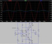
To illustrate the point I’ve attached a screen shot of a basic sim to this post.
The red trace is the output voltage (at 20kHz) and the green and blue traces are the PNP and NPN VAS transistor emitter currents respectively.
The VAS idle current is 10mA and there is about double the AC voltage swing in one VAS transistor than the other due to one Miller cap being 100pF and the other 150pF.
This is a significant imbalance, still, however neither VAS transistor comes close to being cut off.
It probably should also be noted that a common mode signal current that flows in a symmetrical VAS can be induced by any gain imbalance between the positive and negative halves of the circuit and is not strictly a Miller capacitor tolerance issue (Using an alternative compensation scheme just removes one source of error).
This will possibly cause a stink, but IMHO jfets are not desirable devices for the input stage (LTP’s) of fully symmetrical topologies because of this.
The gm imbalance between obtainable N and P channel parts is too great. With bipolar transistors you have scope for linearization with emitter degeneration, which essentially makes gm independent of device parameters (within reason).
Cheers,
Glen
Attachments
Our critics, worry about the 2nd harmonic and ignore the 7th harmonic.
This is like:"Worrying about your beard, when your head could be cut off".
This is like:"Worrying about your beard, when your head could be cut off".
- Status
- Not open for further replies.
- Home
- Amplifiers
- Solid State
- John Curl's Blowtorch preamplifier