The change of absolute phase (I mean in both channels, of course) is audible, an the difference is not small.
Thanks for your efforts Pavel and Mr. Curl for your guidance.
I'm beginning to enjoy this thread...so much to learn.
I'm beginning to enjoy this thread...so much to learn.
EUVL said:I wonder if the distortion spectrum changes if you increase the input voltage swing by, say, 20dB ??
Patrick
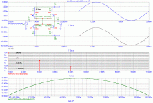
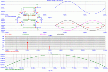
These are input stages, and transfer function is voltage to current. The current is not supposed to change from saturation to saturation. In case you increase output current by 6dB, the distortion is still very low with nice spectrum.
The application is preamp. In case you drive normal power amps, i.e. you need voltage output up to some 2V, again, the distortion is very low and spectrum is nice.
EUVL said:I wonder if the distortion spectrum changes if you increase the input voltage swing by, say, 20dB ??
Patrick
Hereby the answer to your specific question. Please note my previous post.
Attachments
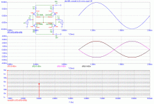
where does the extra 1.5mA come from?PMA said:We have another interesting phenomenon here. Anyone would like to comment?
The voltage source (signal)?
And why is the negative current always very slightly less than the positive?
Change in capacitance with voltage drive?
This is only 1kHz, and capacitances do not have much chance to influence the plots.
The answer is difference in N-JFET and P-JFET halves, as you can see from models used:
*** N Channel JFET
.MODEL 2SK389BL NJF (VTO=-955.83m BETA=12.7099m LAMBDA=1m RS=10.3203
+ CGD=11.2066p CGS=19.1141p PB=3.80937 KF=1.217079E-019 AF=502.753m)
*** P Channel JFET
.MODEL 2SJ109BL PJF (VTO=-418.894m BETA=83.8035m LAMBDA=1m RS=11.0887
+ CGD=71.6975p CGS=61.6464p PB=1.85382 KF=7.879067E-018 AF=499.474m)
Look at VTO and BETA. I wonder if for completely equal devices the distortion would decrease to negligible level.
AndrewT said:
And why is the negative current always very slightly less than the positive?
Distortion by 2nd harmonic in a single device. Cancelled in a diffpair.
so the model is responding to changes.
What other tests can you use to really stretch the model?
What other tests can you use to really stretch the model?
We can do any REASONABLE modification of the models used. In the meantime, we got the answer how to avoid higher harmonics. Keep the N and P devices the most equal. That is what one would expect.
Pavel,
The reason I asked for 20dB more swing was that I was wondering how useful the circuit might be for power-amp VAs applications. With 1k output resistors (in the full blown circuit with folded cascode), one could probably configure an emitter or source follower with useable bandwidth to make a power amp without loop feedback (as Grey is attempting in his GR-25). But as I feared, the circuit is really meant for low voltage swings of a couple of volts.
I do not know spice models well enough, but in my own experience with measuring Toshiba FETs, the P-JFETs have quite different transconductance to the N-devices (by up to 50%) even if they have the same Idss. So I wonder how much those models you used represent real devices, and what happens if the N-JFET has say 33mS while the P-JFET has 42mS.
Also, using cascode devices such 2SK2013 or 2SJ313 at say 70mA and fixed gate voltage, the JFET drains would probably still see an effective R drain of say 2.5 ohms. So I do find the 0.1R that you used in your simulation somewhat too ideal.
Your comments of course most welcome. And thank you for the great work in any case.
Patrick
PS By the way, would you have spice models of 2SK2013 / 2SJ313 ? Could you kindly send me a PM ?
As you could see before:
http://www.diyaudio.com/forums/showthread.php?postid=1481196#post1481196
the N and P models differ in transconductance and threshold voltage. These models were used, only the last example was with BETA and VTO unified, to show the idealized status.
To get as much as shown, we need to keep constant Vds. The circuit example shown few pages earlier is a hint how to do it. In case we put 1k resistor into drains, distortion increase by order and new harmonic component would appear, as also shown by transfer function and distortion analysis on my webpage.
Change of JFET makes not much difference, as long as it has typical transfer function, of course higher transconductance is better.
Anyway, for Vp-p like 20V you have to take into account distortion like 0.01% - 0.1% even with cascoded outputs. Odd order. Only much higher supply rails voltage would help.
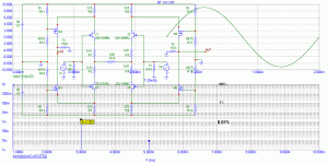
The 1k resistor I was referring to was R20, R21 in the circuit you posted in post# 3859. However, as the cascode devices do not have infinite trnasconductance, as you swing the current in the diff pair, the drain voltage of the JFETs will move a bit, by an amount about the inverse of the transconductance of 2Sk2013 / 2SJ313 at bias. Therefore, I am of the opinion it would be more realistic to use a drain resistor of say 3 ohm in your later, much simplified simulations.
For a poweramp of say 100W class A, one would be looking at voltage swing of say +/- 20V. That would require each of the JFETs to swing +/-10mA into the output resistors (R20, R21). I would expect much higher distortion levels then. Correct ? And higher rail voltage probably won't help as the JFETs are limited by thermal dissipation, making it probably necessary for additional cascode devices to take the heat.
If one were to use something like Grey does in his GR-25, whereby the diff pair is driving both the gate and the source, you have the added non-linearity of the cascode devices coming into play. I have no idea how the distortion would look like, as I cannot find any spice model for the Toshiba 1A MOSFETs.
Patrick
What is the bias current in the cascodes ?
Patrick
PS The Ayre V3 uses MOSFETs in the 1st stage (as one would) and hence has to be driven by separate current sources, as there is no known self biasing P-Mosfet that I know of (DN2540, e.g., would do for N-type). This would not have the benefit of John's way of implementing the diff pair, and I expect to see a different (impaired) distortion spectrum.
The problem with using MOSFETs as the input devices is the capacitance and noise. I thought about doing it in the GR-25, but discarded the idea quickly. On the other hand, you can run a ferocious amount of current through a MOSFET--at least compared to a JFET--and there are MOSFETs that will take any rail voltage that you might care to try.
To me that much capacitance at the input was a deal-killer. Being both bandwidth-limiting and non-linear (hence more distortion), I just didn't want to bother with it. With a JFET input, by the time you get to the folded cascode, you're cruising along at 5 or 6mA...something I wouldn't want to ask of very many preamps if they were faced with a MOSFET at the input. So at least in the case of the GR-25, moving the MOSFETs away from the input allows you to define their environment more completely; you know that you'll have a certain amount of current to drive the Gate/Source and you know what impedance the MOSFETs will be facing.
The 2SK246/2SJ103 JFETs are rated for 50V (quoting from memory, but I think that's right), which is surely more than any preamp needs. If you're willing to go with a balanced/bridged design you can double the voltage swing with the same rail voltage, so for all practical purposes a 50V JFET will do most anything you're likely to need to do--even an amp. The current limitation is a little more troubling. About the only option there is to parallel JFETs. It can be done, but it gets cumbersome. I abandoned that route for the second stage, but never tried it for the input as I didn't feel like I had to have that much current, although it wouldn't have hurt. There's no reason it wouldn't work with matched devices. Assuming that you use Source resistors to balance the paralleled parts, you're going to cut back on the available current, so it's going to be one step back for every two forward.
Another option that pops up is the idea of using a follower input buffer, whether JFET, MOSFET, or bipolar. You don't gain any voltage, but you can arrange things so that the incoming signal now has a known, low impedance and plenty of current to drive the Gates of a MOSFET differential. I didn't want to stick more devices in the signal path just so I could use MOSFETs in the differential.
Grey
Grey,
No objection to using JFETs for the diff pair. Would have done the same. There is a disadvantage -- limited current swing (say +/- 8mA from a bias of say 12mA ?), which means that you cannot get much voltage swing at the output using a "simple" folded cascode like in the circuit in post# 3859, unless you use a large output resistor (R20, R21) of say 2.5k, which in turn make life interesting if you want high bandwidth at the output stage.
I am guessing that is why you use this folded cascode "with a twist" ?
Patrick
- Status
- Not open for further replies.
- Home
- Amplifiers
- Solid State
- John Curl's Blowtorch preamplifier


