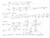
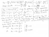
andy_c said:Okay, forget my page 2 in post 3753. By stealing a technique I found in the analysis of a CMOS diff amp, I found a way to get a closed-form expression for the difference mode current Idm in terms of the difference mode voltage Vdm and the FET parameters. This technique avoids splitting the function into regions, which would have happened had I continued with my previous approach. In solving the quadratic equations for ID1 and ID2, I left out some messy algebra. Basically, what happens inside the radical is you end up with the difference of two squares a2 - b2. You then factor this into (a + b)*(a - b). This trick allows bringing the term involving Vdm outside the radical, which then allows exposing the difference mode current expression as an odd function.
Here's the completed analysis. My original page 1 is okay.
One step further. All is left is to get the Fourier transform of the inverse square sin(wt) and calculate the Idm spectra. I don't have at hand a Fourier transform table of square integrable functions, it should be avalable somewhere on the Internet.
Attachments
Good work, Syn08, and others in helping with this process.
This is my proposal, interest, whatever. 😉
I want to compare a single fet with a diff fet pair, first using ideal fets.
I also want to compare single bipolar with a diff bipolar pair. This has already been done by Meyer, Pederson, etc. and is taught in class.
I did not, at first, realize the Dr. Pederson had already derived the diff fet example with ideal mos fets, and this should work OK, IF I can just compare it accurately to a single fet example, which looks a little different in assumptions, etc. Please understand, I am working with the class notes of 3 professors over a 37 year period. For many of you, link the UCB 141 class notes put here earlier, to get started. Go to post 3734 on this thread.
Then we can compare the differences between all 4 configurations and get a base line.
Later, we can add complications, such as higher order distortion, local degeneration, and imperfect devices both in transfer function and for nonlinear beta in bipolar devices.
OK?
syn08,
In you last derivation, are you trying to expand the square root
for when Vdm is sufficiently small ? If so, you didn't do the expansion correctly.
One way to see that there is a problem is to note that
the right-hand side goes to infinity as Vdm goes to zero.
Instead, the correct formula will end up with sums of terms that
have positve powers of Vdm on the right-hand side.
BTW, this would eliminate the need to
find the fourier transform of 1 over the sin squared, which
is problematic because it is a function that goes to infinity twice per period.
Some quick and dirty simming,Test freq 20Hz. Components below 1e-8 discarded.
Single FET 2N3819, Vds=10V, bias 2mA, drive 300mV, output 900uA
Harmonic Normalized Normalized
Number Component Phase [deg]
2 5.603e-02 -90.00°
3 1.912e-05 -0.02°
Total Harmonic Distortion: 5.603103%
Single BJT 2N3904, Vce=10V, bias 1.24mA, drive 12mV, output 0.5mA
Harmonic Normalized Normalized
Number Component Phase [deg]
2 1.017e-01 -90.00°
3 6.793e-03 -180.00°
4 3.271e-04 +90.00°
5 1.150e-05 -0.03°
6 2.650e-07 -89.02°
Total Harmonic Distortion: 10.197369%
FET Diff 2N3819, Vds=10V, bias 2mA each (4mA CCS), drive 300mV total (150mV per leg), output 900uA
Harmonic Normalized Normalized
Number Component Phase [deg]
3 1.593e-03 -0.00°
5 1.279e-06 +180.00°
Total Harmonic Distortion: 0.159281%
With full 300mV drive per leg THD=0.65 and 1.75mA output
BJT Diff 2N3904, Vce=10V, bias 1.24mA each, drive 12mV total, output 0.5mA
Harmonic Normalized Normalized
Number Component Phase [deg]
3 3.501e-03 -0.00°
5 1.453e-05 +0.01°
7 6.067e-08 -2.16°
Total Harmonic Distortion: 0.350102%
Doubled drive: THD 1.4% and 1mA output
Interresting is the different phase relationship of the harmonics with FET vs.BJT.
- Klaus
P. Lambda said:syn08,
In you last derivation, are you trying to expand the square root
for when Vdm is sufficiently small ? If so, you didn't do the expansion correctly.
One way to see that there is a problem is to note that
the right-hand side goes to infinity as Vdm goes to zero.
Instead, the correct formula will end up with sums of terms that
have positve powers of Vdm on the right-hand side.
BTW, this would eliminate the need to
find the fourier transform of 1 over the sin squared, which
is problematic because it is a function that goes to infinity twice per period.
Not necessary, that's the generic Taylor expansion for sqrt(x^2+a). It was used in computers for calculating sqrt(x) with an arbitary precision, today there are better/faster convergence algorithms. Epsilon is not a very good notation, it is reserved in calculus for infinity small quantities. I don't have the proof for this expansion but I guess it assumes x # 0.
I'll check again the whole thing next week.
ideal diff fet pair
Hi John,
Using ideal FETs (and no source series resistors) the distortion is zero, as the difference of two squares gives a linear characteristic:
(x+y)^2 - (x-y)^2 = 4xy. If we held x constant, the difference is linear in y.
See also the articles about the D2S amp in:
EW+WW, Jan. 1994, pp. 82-84. and
EW+WW, Sept. 1995, pp. 751-756.
Cheers, Edmond.
john curl said:[snip]
I want to compare a single fet with a diff fet pair, first using ideal fets.
[snip
Hi John,
Using ideal FETs (and no source series resistors) the distortion is zero, as the difference of two squares gives a linear characteristic:
(x+y)^2 - (x-y)^2 = 4xy. If we held x constant, the difference is linear in y.
See also the articles about the D2S amp in:
EW+WW, Jan. 1994, pp. 82-84. and
EW+WW, Sept. 1995, pp. 751-756.
Cheers, Edmond.
Ok, this method requires much more algebraic manipulation, but leads to a consistent final result (ratio of the even harmonics, here the 3rd and the 5th, to the fundamental).
The function is "odd" f(-x)=-f(x) so (as expected and confirmed by simulation) it generates odd harmonics only. Interesting enough, there is a slight reduction of each odd harmonic by a upper (odd) harmonic products negative contributions.
This is a large signal analysis, so a more detailed version should consider only variations around a bias point. This will make the harmonic ratios Ai/Ao i=3,5,... dependent on the signal amplitude.
Attachments
Re: ideal diff fet pair
EDIT/Note : those are NOT curves for a diff arrangement.
- Klaus
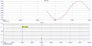
But one has to hit the right bias to get there, see attached plot (for the IRFP244 models by andy_c). Only with optimum bias one gets a flat gm over the widest range. Underbias makes it more curved (bottom trace) but at least with monotonic curvature, while overbias gets us a bigger range within a choosen gm tolerance band vs drive, at the cost of non-monotonic curvature which will produce more of higher order harmonics. So D2S bias gives better results in the small signal regime, while slight overbias yields less total distortion at larger excursions. With degeneration one gets always the overbiased shape of the curves for reasonable bias and drive levels.Edmond Stuart said:Using ideal FETs (and no source series resistors) the distortion is zero, as the difference of two squares gives a linear characteristic:
EDIT/Note : those are NOT curves for a diff arrangement.
- Klaus
Attachments
My conclusion: D2S works only with drive applied directly as Vgs, hence not with a diff pair. Do I miss something?
The amp proposals in the Hegglun article are also non-diff arrangements, btw.
The amp proposals in the Hegglun article are also non-diff arrangements, btw.
diff
Although, depending on the definition of 'diff', I don't disagree with you.
KSTR said:My conclusion: D2S works only with drive applied directly as Vgs, hence not with a diff pair. Do I miss something?
The amp proposals in the Hegglun article are also non-diff arrangements, btw.
Although, depending on the definition of 'diff', I don't disagree with you.
- Status
- Not open for further replies.
- Home
- Amplifiers
- Solid State
- John Curl's Blowtorch preamplifier