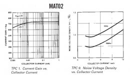
PH, I should have said 'beta peak' or the current where the beta is maximum. I have the graph in front of me, because Analog Devices used to think that such data was important to design engineers.
This is an exceptionally LOW 'beta peak current', as most small signal transistors peak at 4 ma or so, and many popular transistors peak at 50 ma or so. This is why I asked Scott the question in the first place about his AD797. Now, this may make it more clear, as to why I needed this info.
This is an exceptionally LOW 'beta peak current', as most small signal transistors peak at 4 ma or so, and many popular transistors peak at 50 ma or so. This is why I asked Scott the question in the first place about his AD797. Now, this may make it more clear, as to why I needed this info.
I still have a small stash of the original AD devices. Love those metal cans with gold-plated leads.
Graph - me too, at least for the AD820 series. It's pretty dog-eared by now. For the NPNs, I only have a brochure-like thing for all the old AD duals.
It seemed low - and thanks for mentioning that.
Graph - me too, at least for the AD820 series. It's pretty dog-eared by now. For the NPNs, I only have a brochure-like thing for all the old AD duals.
It seemed low - and thanks for mentioning that.
They are pretty nice devices. Audible Illusions made a comp diff power amp with them, about 20 years ago. I used to match them as a comp pair, when I worked there, part time.
John -- do you have any idea/guess how closely the VBE of the transistors in one AD810 might match another - separate - AD810?
Thanks
Phil
Thanks
Phil
Anywhere above 100 ua, I would guess, but isn't that the exception, not the rule? Or is every AD component that good?
PH104, I suspect they would track fairly closely. The big problem for me has been the Vbe 'matching' of the NPN's to the complementary PNP's. It seems to me that time constants in fabrication would really make the difference in any NPN's, so batch to batch might be slightly different.
In 'Stereophile' April issue, Scott's and my good buddy, Richard Sequerra, is interviewed.
Good reading, especially because of the commentary about Barney Oliver and his amp design on p. 58.
Good reading, especially because of the commentary about Barney Oliver and his amp design on p. 58.
john curl said:PH104, I suspect they would track fairly closely. The big problem for me has been the Vbe 'matching' of the NPN's to the complementary PNP's. It seems to me that time constants in fabrication would really make the difference in any NPN's, so batch to batch might be slightly different.
Since the gm of a bipolar has nothing to do with absolute Vbe, I don't see how this would matter. I would think 60mV or so would be the most difference you could ever see.
I'll be near a newsstand Saturday, I'll try to take a peek. Last time I was in Denmark I tried to scan an issue of Elector while waiting for a train and the clerk threw me out of the store (she was quite rude).
Terry Demol said:
Agreed Bob.
Even though the dominant pole might be at a very LF the amp can
still have extremely low HF (20kHz) distortion characteristics and
be characterised as 'fast'.
Now, what if we were to get such an amp and resistively load the
VAS so the pole shifts nearer to or above 20kHz. This should
bring the distortion flatter over the audio band and less tilted up
at high frequencies.
One thing I notice about the Dart Zeel and the Ayre MXR open loop
amps that both got rave class A reviews - is their distortion,
although comparatively high, is almost entirely independent of
frequency.
Very few amplifiers exhibit this characteristic.
cheers
Terry
Hi Terry,
You make an interesting observation.
Yes, interesting things happen when one resistively loads the VAS. The open loop pole moves up in frequency and the low-frequency NFB decreases. With NFB flat across the audio band, to first order one gets the distortion to be flat across the audio band.
Of course, the distortion is then less tilted up at high frequencies because we no longer have the situation of the NFB decreasing as frequency increases. BUT, the removal of the tilt has occurred because the distortion at lower frequencies has been made higher, leveling it with distortion at high frequencies.
So, loading the VAS resistively did not decrease high-frequency distortion.
Another interesting thing that happens with the resistive loading is that the input stage is now made to work harder at all frequencies, not just at the high frequencies. This again will tend to increase distortion at low frequencies.
A last interesting thing that happens that could conceivably make the high-feedback and low-feedback amplifiers sound different (not necessarily one better than the other) is the alteration of the phase relationships in the forward path in the two cases.
When you have the wide open-loop bandwidth, the signal fed forward in the open loop amplifier is pretty much a replica of the input signal, at least for stimulous that is limited to the audio band. In the case of high feedback and low open-loop bandwidth, the signal fed forward no longer looks like the input signal; it looks more like a differentiated version of the input signal. The shape of the signal is different. The signal in the latter case will get its different shape due to the error being smaller much of the time. Putting it yet another way, the phase relationship of the error component and the signal component of the forward signal are different in the latter case.
Although this waveshape issue does not cause measurable distortion to be increased (including TIM), if there was some poorly-understood process at work that was sensitive to the error vs signal phase, one might hear an audible difference. This is highly speculative, but is no more so than speculation about why two cables that measure identically may sound different.
Cheers,
Bob
I have lower THD with VAS resistor loaded compared to unloaded. Speak about same gain after NFB applied. There is an optimum of loading resistor value. The openloop circuit is wideband, however.
Bob Cordell said:
When you have the wide open-loop bandwidth, the signal fed forward in the open loop amplifier is pretty much a replica of the input signal, at least for stimulous that is limited to the audio band. In the case of high feedback and low open-loop bandwidth, the signal fed forward no longer looks like the input signal; it looks more like a differentiated version of the input signal. The shape of the signal is different. The signal in the latter case will get its different shape due to the error being smaller much of the time. Putting it yet another way, the phase relationship of the error component and the signal component of the forward signal are different in the latter case.
Cheers,
Bob
Wouldn't you say that the best situation is when the output waveform is a replica of the input one?
I would think that the signal relationship between feedback and input is very important, the common mode on the input pair has a big effect on the overall distortion. Inverting amplifiers usually have less distortion because of the lack of common mode signal.
I'm on the run, but wanted to drop in a note that I managed to locate the CCS article I mentioned yesterday. It was indeed Walt Jung. It is (or was) available in two parts as PDF files from his website. It was originally published in audioXpress in 2007, so some may have it in the original hardcopy.
Grey
Grey
Joshua_G said:
Wouldn't you say that the best situation is when the output waveform is a replica of the input one?
Hi
It was not a very good explanation by Bob, and it could confuse somebody, but he is talking about the fed forward signal, not the output signal.
Bob Cordell said:
A last interesting thing that happens that could conceivably make the high-feedback and low-feedback amplifiers sound different (not necessarily one better than the other) is the alteration of the phase relationships in the forward path in the two cases.
When you have the wide open-loop bandwidth, the signal fed forward in the open loop amplifier is pretty much a replica of the input signal, at least for stimulous that is limited to the audio band. In the case of high feedback and low open-loop bandwidth, the signal fed forward no longer looks like the input signal; it looks more like a differentiated version of the input signal. The shape of the signal is different. The signal in the latter case will get its different shape due to the error being smaller much of the time. Putting it yet another way, the phase relationship of the error component and the signal component of the forward signal are different in the latter case.
Although this waveshape issue does not cause measurable distortion to be increased (including TIM), if there was some poorly-understood process at work that was sensitive to the error vs signal phase, one might hear an audible difference. This is highly speculative, but is no more so than speculation about why two cables that measure identically may sound different.
Cheers,
Bob
Been wondering about that 90 degree phase change above the dominant pole. I thought I read before in some post that that phase change was desirable, but I haven't been able to locate the post. I was wondering if that phase change is what the issue was regarding the argument between low open loop and high open loop bandwidth. If this is the case, then why not two pole compensation to keep the in band phase constant?
Joshua_G said:
Wouldn't you say that the best situation is when the output waveform is a replica of the input one?
Hi Joshua,
You're right, but the waveform I was referring to is an intermediate waveform in most amplifiers. I'm sorry I was not clear enough about that. In a typical Miller-compensated amplifier with low open-loop bandwidth, the signal that is not a reasonable replica of the input signal is just the current signal that exists between the input stage and the VAS. The output of the VAS in such amplifiers is a good replica of the input signal, as is the output of the amplifier.
It's worth noting that there are many audio systems in which intermediate signals exist that are not good replicas of the input signal. Perhaps the best example of this is on the phonograph record, as a result of RIAA equalization. The RIAA equalization at the recording studio boosts the highs and cuts the lows, largely like a differentiator function. The essentially-differentiated signal then undergoes all of the nonlinearities of the physical recoding process. On playback, the RIAA equalization is much like an integration to restore the signal to its original waveshape. If you were to record a low-level square wave on an LP and then look at the signal at the cartridge output, it would look a lot like a differentiated version of a finite-bandwidth square wave.
Cheers,
Bob
The three audio products from his youth days could well be nominated for the most shabby and unreliable looking US manufacture (export) gear ever.
There was a lot of competition in those days.
- Status
- Not open for further replies.
- Home
- Amplifiers
- Solid State
- John Curl's Blowtorch preamplifier