
john curl said:Steve, I helped design the equipment.
So? You said you doubted that they had ever used transformers in making a record or CD. That implies that you don't know for certain.
You are completely ignorant of their recording process.
You're right, I don't know exactly what their recording process is. But I think I'm pretty safe in assuming that it starts with microphones. Did you design their microphones? If not, what microphones are they using? As I said, the microphones are the first point in the chain where you're likely to encounter transformers.
se
B&K for Crystal Clear. Schoeps for Wilson. MY microphone and mixer electronics. MY 30 ips master recorder electronics for Dave Wilson (Ultramaster). The only question is on the Ortofon disc recorder electronics input, and whether it could be bypassed.
Steve seems to be silent. He has been shown low level distortion and special drive and its result.
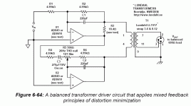
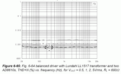
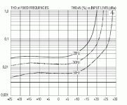
Actually you have to look at .05-.1V to see the RISE in low frequency distortion with lower level. Can you do that? Also, if you go to the data sheet of the JT-11P1. On page two you will see what I mean in the graph of thd vs input level at 20Hz and -15dB, 0dB being +4dbu.
PMA said:
This is no surprise when compared to SE loopback, and limited to 100kHz. Have you also tried exactly balanced input for loopback spectrum?
Yes. The difference isn't as dramatic, for sure. But I don't have any balanced music sources nor do most other people. I don't find the difference at line level through reasonable interconnect lengths to be that important.
Steve, language difficulties. "At lower levels" is different than "with lower levels," but yeah, it can be taken both ways. The nice thing about the input transfomer for preamp use is that the LF distortion at (say) 6dBV is still something like 0.02% at 20 Hz, nearly all third harmonic. I wish my subwoofers were that good. And as PMA hints, with no fuss or bother, both balanced and unbalanced sources can be accommodated.
Your evangelizing paid off in my case.😀
PMA said:Now silent?
Well yes, temporarily.
I had to run up to the store to get some more red lettuce so I could finish my turkey and swiss on dark rye sandwich and have a bit of lunch.
My apologies for keeping you sitting on the edge of your seat. I'll go reply to your post now.
se
Good work, PMA. I have seen 'worse' from Jensen, but they don't appear to publish those results anymore. Deane, himself, was a pretty open and honest guy, in my opinion. These are uncomfortable disclosures for any manufacturer, and apparently they have gotten lost.
PMA said:"Special drive" result.
Yes.
There's another approach however that's more elegant (in my opinion) and more effective.
This other approach doesn't just say "Hey, we've got some distortion. Let's throw some negative feedback at it and reduce it!" Instead, it recognizes what the source of the distortion is and deals with it more directly.
In this case, the source of the distortion is ultimately the DC resistance of the transformer's primary windings. The distortion is the voltage dropped across this resistance by way of non-linear current induced through it by way of the transformer's core.
This other approach deals with this by driving the transformer with a negative impedance equal to the DC resistance of the transformer's primary windings and effectively removes the winding resistance from the equation.
This other approach, somewhat ironically, is what is used in the Audio Precision rig that Walt used to make the measurements for his feedback approach.
In any case, all of this presupposes that the distortion without the special drive is problematic in the first place. At least in the context we're discussing here.
Sure, if you're wanting to make a precision measurement instrument like the Audio Precision, you want to eliminate as much distortion as possible.
But in this context, does reducing all harmonic distortion to such vanishingly low levels provide any real benefit at the end of the day or does it really just do nothing more than satisfy the sensibilities of an engineer?
Q: "Why did you climb to the top of that mountain?"
A: "Because it's there."
Similarly,
Q: "Why did you reduce distortion to such vanishingly low levels?"
A: "Because I can."
se
PMA said:Steve seems to be silent. He has been shown low level distortion and special drive and its result.
You see? That's what prejudicial assumptions get you.
Steve was silent simply because he wished to eat lunch.
And now, I'm going to be silent again for a while. Not because you've shown me how big your manhood is, but because I'm taking my dog over to the park.
I'll be silent again a bit later when I eat dinner. But I'll be sure and let you know beforehand so your imagination doesn't start running wild again.
se
Steve Eddy said:
Yes. But consider why that is the case.
First, they only use just a handful of turns as opposed to the thousands of turns you'd find on an audio transformer. They do this not only because they can due to coupling efficiency being so much higher at such high frequencies, but also because if they used thousands of turns, the RF signal would be eaten up by the winding capacitance.
Second, they use powdered ferrite cores. That's because laminated cores would be much too lossy due to eddy currents induced into the laminations.
Just the handful of turns means that the transformer's primary inductance will be exceedingly small and at audio frequencies would be little more than a short circuit.
Bottom line, just as RF transformers make for useless audio transformers, audio transformers make for useless RF transformers.
That's not to say that an audio transformer can't couple RF. They can, but it's not by way of transformer coupling. That path is just too lossy at RF. Instead they can couple RF through capacitive coupling due to interwinding capacitance. But then that's why the better input transformers have electrostatic shields between their primaries and secondaries.
Sure. Just send me your 2GHz signal generator and your 2GHz 'scope.
Either that or I can send you a transformer and you can do it.
se
What I find interesting in this context is that the output signal from my Audio Precision, the signal that is clean down to -120dB, 10Hz-200kHz, up to 15VRMS into 600 ohms, is coming out of an output transformer...
@Steve: That's indeed how AP does it. Patent by Bruce Hofer IIRC, # 04614914. Sorry, saw your post just now.
Jan Didden
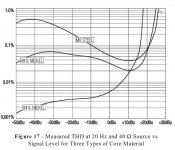
The amazing thing about analog magnetic tape and class A electronics (whether tube, fet, or bipolar) is that is reduces predictably in level with lower amplitude. So when a magnetic tape is perhaps 10db below operating level, the distortion has reduced 10 times from 0 Vu (+4) level. 16 dB would be 40 times lower level, 20 dB 100 times lower level.
Now let us say that a magnetic tape gives .5% distortion at 0 Vu. The predicted distortion at 20 Hz would be .5/40 = 0.0125% distortion. A typical Jensen transformer gives 0.025% under the normal drive conditions, a factor of twice the magnetic tape.
Now what about a Blowtorch preamp.
Let us say that 0.1V out is 1W or 94 SPL from the loudspeaker. Let me guess that I 'might' have .5% distortion at 1V out, almost all 3'rd harmonic (just like tape). Then, at 0.1V, the distortion can be accurately predicted to be 100 times lower or .005% distortion. Yet, a tranformer in series with the output would add .025% at 20Hz, .015% at 30Hz, .005% at 50 Hz.
You see, the transformer adds double the distortion and MORE at low frequencies. Of course, negative impedance drive can be used, but it is tricky, and will oscillate if you are not careful.
john curl said:[snip] Of course, negative impedance drive can be used, but it is tricky, and will oscillate if you are not careful.
It is not tricky, completely predictable, and any half-witted designer knows how to make it stable. We are doing negative feedback successfully from before you were born, John. What a concept! 😉
Jan Didden
For the record, transformers INCREASE in low frequency distortion at lower levels. EVEN JENSEN.
Check your books, John
http://www.jensentransformers.com/an/Audio Transformers Chapter.pdf
Attachments
john curl said:Jan, negative impedance drive, what is it, and what is dangerous about it?
It's in patent # 04614914. I don't know about dangerous. It seems to work very good in 1000's of pieces of equipment around the world.
BTW Erno Borbely told me he enjoyed the time he had with you in Switzerland discussing the best transistors for your products.
Jan Didden
- Status
- Not open for further replies.
- Home
- Amplifiers
- Solid State
- John Curl's Blowtorch preamplifier