Charles Hansen said:
The curves for the FETs shown in the Sony paper are very similar to the curves for the Toshiba J74/K170 pair. (I know these are not suitable for this application, but they are the only datasheets I have handy for both polarities of FETs.) Basically, the N-channel parts have a sharp knee in their gate leakage current at around
Charles do you have the reference? This technique seems fraught with all kinds of problems. My search of internet Sony schematics turned up nothing (though I did find a Sony mike that used the Neumann charge amplifier style input).
To the best of my knowledge, Sony used more conventional techniques for their real-world industrial mikes. I have the schematics for the Sony C37, C48, and C500 microphones and they use a single fet follower design with about 1G total resistance. T
scott wurcer said:Charles do you have the reference?
Assuming your e-mail address hasn't changed in the last 3 or 4 years, you should have a copy of the paper in your in-box.
john curl said:To the best of my knowledge, Sony used more conventional techniques for their real-world industrial mikes. I have the schematics for the Sony C37, C48, and C500 microphones and they use a single fet follower design with about 1G total resistance. T
I did a quick search of the internet last night and was unsuccessful in finding the model that used this circuit. However, I do remember that it existed. The circuit was mentioned in the product brochure, and I got the service manual for it. As I recall, the FETs were special ones that Sony made for this application, and they were quite expensive (around $20 each in the '70s). I was hoping that somebody here would remember the model number of the microphone.
scott wurcer said:Charles that's why I posted my circuit. It's a very simple updated version of what Neumann was doing with some of their KM series mikes. I know you hate it but feedback works for other things too.
I just glanced at it so I could be wrong, but I believe that the circuit is bootstrapping the input to increase its input impedance. That is what started this whole exploration for me 35 years ago.
I used to play in bands and do some recording. I also worked at a NASA subcontractor where we used B&K mics to to measurement work. It was clear to me that a small tensioned diaphragm with a resonant frequency outside the audio band was inherently going to give better fidelity than a large-format diaphragm with in-band resonances.
But all of the B&K preamps used circuit techniques that were known to sound bad even back then. (Face it -- there is a reason that the vintage tube mics are still in demand -- the circuits sound better!) So I was interested in trying to make a good circuit that would work with a B&K capsule.
The best starting point I could find was the Sony technique of complementary followers. I bought a bunch of parts to build the things but never finished the project. So I'll never know how it would have sounded....
The point of all this rambling is that I'm sure your circuit works fine. It probably even sounds pretty good. But is it the best sounding circuit out there? Probably not, based on my experiences.
But we are straying pretty far from the Blowtorch at this point....
An interesting site:
http://www.gyraf.dk/schematics/schematics.html
I heard too by Jörg Wuttke from Schoeps, that Sony had copied his microphones series it was about 20 years ago.
http://www.gyraf.dk/schematics/schematics.html
I heard too by Jörg Wuttke from Schoeps, that Sony had copied his microphones series it was about 20 years ago.
Charles Hansen said:
I just glanced at it so I could be wrong, but I believe that the circuit is bootstrapping the input to increase its input impedance. That is what started this whole exploration for me 35 years ago.
No it's a charge amplifier like the one used in precision quartz accelerometers. 100% GNF the gain is Ccapsule/Cfeedback there is no bootstrapping involved. It's like an op-amp inverter with two resistors, gain = Rf/Rg except the "resistors" are two capacitors.
Same idea as Neumann KM86 in previous link except I have added op-amp for lots of OLG and use the FET just as the impedance converter.
If you want to talk tube mikes, virtually everone in the industry who loves or hates them will go on at length at their obvious colorations, they truely are another musical instrument.
The bootstrapping is also to reduce effective dead capacitance. Delta C/C (I know you still think I am deluded or something, BUT deltaC/C still exists.) Erling Fredriksen had to clue me in about it, decades ago, and I, too, would have missed it, if he had not.
Thanks Charles for the article. I spent more than one hour today with AES preprints before giving up.
Thanks Charles for the article. I spent more than one hour today with AES preprints before giving up.
john curl said:The bootstrapping is also to reduce effective dead capacitance. Delta C/C (I know you still think I am deluded or something, BUT deltaC/C still exists.) Erling Fredriksen had to clue me in about it, decades ago, and I, too, would have missed it, if he had not.
Thanks Charles for the article. I spent more than one hour today with AES preprints before giving up.
That's the beauty of the inverting configuration the input capacitance doesn't load the source. It figures into the noise gain a little so you still can't go crazy on the FET.
That Sony circuit is what I thought, they are running the N-channel into impact ionization and using the fact that the P channel does not have it due to it's different mobility. I wouldn't consider that manufacturable, I gather they didn't in the end either. For all that trouble the noise is not very good and to boot they ended up with two 1k degeneration resistors.

If people think this stuff is too OT I'll stop now.


Yes, but low input impedance and/or resistor noise make the inverting topology often unusable.
No Scott, we are making progress. Many here will not need to know everything about microphone design, but it shows the pitfalls of hi Z design. I, too, found the Sony article VERY focused on the input, yet the noise level was not so good, and I suspect distortion was not so very good as well. I could easily make a better overall design.
BTW, I made several high Rin amps for quite different purposes, monitoring of transient el. fields with capacitive sensor in some distance from HV power lines 😉
scott wurcer said:If people think this stuff is too OT I'll stop now.


Please carry on - I'm fascinated. Over the past year I've been working with charge amplifiers...
Yup it is certainly on topic in that it's at least about electronics and audio to a greater extent than many posts here 😉
Noise Analysis
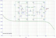
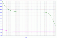
Let's kindly get back on topic. Here is my small contribution to noise analysis. The plot shows V(out1) SE output noise in nV/sqrtHz vs. frequency, input is V1.
P.S.: this is an output noise, so to get more common input noise one has to divide by gain.
Let's kindly get back on topic. Here is my small contribution to noise analysis. The plot shows V(out1) SE output noise in nV/sqrtHz vs. frequency, input is V1.
P.S.: this is an output noise, so to get more common input noise one has to divide by gain.
Attachments
This is not the quietest circuit in the world, because the mosfets on the output will contribute significant 1/f noise. This can be fixed, but the solution is worse than the problem, except for a slight noise improvement.
John, I am aware of what you are saying. IMHO the result is very very good, because even with MOSFET contribution noise seems to be 7nV/sqrtHz (input).
This is better than most of JFET opamps.
This is better than most of JFET opamps.
john curl said:This is not the quietest circuit in the world, because the mosfets on the output will contribute significant 1/f noise. This can be fixed, but the solution is worse than the problem, except for a slight noise improvement.
Thought question on noise, how would you make a gain of 6dB inverter (a real inverter with 100% GNF) with 1nV/rt-Hz input referred noise? |input impedance|>10k @ 20kHz also required.
- Status
- Not open for further replies.
- Home
- Amplifiers
- Solid State
- John Curl's Blowtorch preamplifier

