Ah, there's the problem, not revealing enough 🙂 (or you're deaf)
Regarding your driver's ability to reproduce a square wave....
There is only one place to measure... on the axis you are listening and excluding the room influences..... meaning near-field measurement... 3 feet might be OK.
Dont expect to see a square wave. Very few speakers can do it. Use a mid range freq,,, 400-1 Khz.
Since you dont have any control of the signal ampl and phase.. it is what it is.
There just happens to be an article on this ability to reproduce a square wave....
A Loudspeaker That Can Play Square Waves? | audioXpress
Using DSP technology, it can get the phase etal pretty good on a sample speaker.
THx-RNMarsh
Last edited:
Not that it matters, but at that moment in time the system was:
Elac discovery ds-s101g server/streamer/dac
Pangea rca out
Yamaha R-N803 YPAO integrated- Burhoe Acoustics/Blues (slightly modified)
Sonance sonamp 260- 2x10” precision power Sedona subs
Green Monster cable speaker wire (The Hulk edition) 😛
Ended up with Cardas 101
Mostly Home Theater gear, isn't it? Interesting choice for revealing acoustic fine details like cables, I thought Home Theater stuff is mid-fi at best? I don't think it's worth investing in Bybees with this system. Bybees don't improve a system that's under 25k, they are very selective.
nothing home theatre about any of it......the yamaha is a 2.1 integrated with dsp.....it stomps the parasound halo integrated head to head.
actually for the money I couldn't recommend it enough.
actually for the money I couldn't recommend it enough.
Hey George,
No corrosion on the contact end, I clean and use corrosion protector fairly regular since we live a few hundred feet from the Gulf of Mexico.
And although semi transparent I didn’t really notice it until I redid the ends one day....then found it ran the entire length. Replaced it with some decent 14awg ofc and found the difference quite surprising.....I wouldn’t wish that cca (I got mistakenly) on anyone, even on syn08! 😀
Monster XP is roughly equivalent to 18 AWG so there is a significant different on DCR. Still the corrosion would increase the DCR if its severe enough. The fine gauge wire will corrode through faster that a wire with thicker gauge strands.
Measure Ls/Rs 1khz to 100khz, with very careful shorted cal. (Note, I find that I have to redo a shorted cal at every frequency I run).Duplicate with a brand new identical gauge zip. Any litz style effect should show inductance change at the higher frequencies. You must have repeatability at the 10 nH level. That will not be possible below a kHz or so, but as freq rises, repeatability and accuracy will improve.
Sweep a pure sine 20 to 100khz, 2 or 3 amps peak into a 4 ohm pure resistance. Look for increased noise in the dirty cable as freq goes into the changed Rs regime. Expectation from back of envelope calcs is anywhere from 10e-2 to 10e-4 below drive frequency levels.
Oh, btw, use some plumbing flux to solder the ends to a new copper surface, the RA flux is needed to cut the surface garbage and take contact issues out of the equation.
I was hoping you'd do the waveform modulation sideband thing though, as your contact friend did support the back half of the premise.
Jn
Just to confirm the basics. measuring 1 strand of a wire its mostly meaningless. You are asking for a measurement of the loop with one end shorted I believe. Then add 4 Ohms and drive it looking for artifacts.
I could not find any zip cord in my junk pile but I have other places to look. I confirmed I can measure down to a pretty low inductance with 10 nH resolution. I tried a spool of 24 AWG Teflon/silver plated copper as a starting point. 1 KHz with 69.973 uH and 12.07 Ohms, 100KHz gave 69.767 uH and 18.090 Ohms. Still the last few digits may be dominated by noise. Getting consistent measurements will be a test of experimental care, accuracy and precision so not quick. Still could be interesting.
I did not understand your remark about Litz wire having more inductance at HF. My experience with inductors has been that properly sized litz has more consistent inductance vs. frequency. Consistently more that even foil type coils.
As new as 2012. You could point to the Stereophile review: Quad Reference ESL-2805 loudspeaker Measurements | Stereophile.com
All my speakers are time aligned since 1970. KEF, Elipson, home made.Have you tried it?
For subs, it is not an issue, The wavelength is long enough.
For low-high crossover, the way I do:
- Align the speakers vertically and horizontally (if no DSP) to get the center of the moving coils on a vertical line.
- Put your measurement mic at 1m. in the center of the line between the center of two ways. This line has to point to the ears at listening position.
- Set the frequency generator at the crossing frequency.
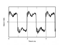
- Align your speaker back and forth to get the best square wave as possible. Ot play with the delay if you prefer to use a DSP.
As an example, in the KEF LS50 wireless (coaxial drivers equipped with a DSP) the delay is optional (on/off). The difference is obvious.
Last edited:
Scorpion, everyone understood that "new" was used in opposition to the "old" model.As new as 2012.
I was aligning a loudspeaker design 45 years ago, and I was not the first. All you have to do to know what NON-aligning speakers does to the sound is to use a pair of K-horns, like I did for 10 years. While Quad could always do a pretty good square wave, most loudspeakers don't do as good a job, but it does not have to be perfect.
I want to thank Richard for his links and pictures because I do not have all of them in my files. He and I are old men, who did our greatest work in audio 40 years ago, when we had the energy and resources to do it. We have acquired wisdom from experience, combined with measurements, certainly more than many of you, so cheap snipes do little but show the emotional maturity of the snipers.
I want to thank Richard for his links and pictures because I do not have all of them in my files. He and I are old men, who did our greatest work in audio 40 years ago, when we had the energy and resources to do it. We have acquired wisdom from experience, combined with measurements, certainly more than many of you, so cheap snipes do little but show the emotional maturity of the snipers.
Loudspeakers' relative time or axial alignment isn't a single number, and also not at the voice coils' location. One (of many) approximations, since we have to choose something, is to feed both (level matched) drivers the same, but inverted, narrow band noise centered on the intended crossover frequency and to adjust position for best null on the intended axis. This can even be done by human ear-ball.
One advantage of this method is that it soon convinces the experimenter of the fuzziness of the concept.
All good fortune,
Chris
One advantage of this method is that it soon convinces the experimenter of the fuzziness of the concept.
All good fortune,
Chris
All depend of the crossing frequency and slopes of the filters. If it is between 700 to 1500 Hz (my prefered) and 12/24dB/oct slopes, moving coil alignment is a good start.One advantage of this method is that it soon convinces the experimenter of the fuzziness of the concept.
Your tip to put the speakers out of phase during the measurement time is a good one.
I have already posted this group delay curve of a Moonaudio speaker, time aligned with DSP.

Last edited:
I'd actually suggest starting without the crossover filters, just drivers. It may not be ideal, or even the best compromise, but it gives us a place to stand, and lets us think in conventional filters.
All good fortune,
Chris
All good fortune,
Chris
Scorpion, everyone understood that "new" was used in opposition to the "old" model.
yep
-RM
I was aligning a loudspeaker design 45 years ago, and I was not the first. All you have to do to know what NON-aligning speakers does to the sound is to use a pair of K-horns, like I did for 10 years. While Quad could always do a pretty good square wave, most loudspeakers don't do as good a job, but it does not have to be perfect.
I want to thank Richard for his links and pictures because I do not have all of them in my files. He and I are old men, who did our greatest work in audio 40 years ago, when we had the energy and resources to do it. We have acquired wisdom from experience, combined with measurements, certainly more than many of you, so cheap snipes do little but show the emotional maturity of the snipers.
Thanks. All true.
-Richard
Why ? Crossovers and their associated filters are part of the phase turns. Response curves and phase turns are heavily correlated.I'd actually suggest starting without the crossover filters, just drivers.
It is a work of successive approximations
Last edited:
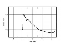
As new as 2012. You could point to the Stereophile review: Quad Reference ESL-2805 loudspeaker Measurements | Stereophile.com
To address some of your complaints about my writing style ---- I could but what for? I still have the QUADs and could do the tests but why should I when it is there and at other places ready to show you at the click of a mouse.
I also do not assume all you say is your own original thought or work. I have yet to read an original thought from you.
I find data and show it just to back up my point(s)... usually from past tests and experience. I know the result before I look for it and just hope to find others have by now done same and I dont have to do it again.
I did describe how to do an alignment on a multiple speaker system, manually (without DSP). Just need to design your own variable slope and freq cross over and be able to move drivers physically. I designed and built it myself. for myself just to know. There were none available nor DSP.
The reason for continuously variable slope is because the driver has its own phase slope and combined with a cross-over phase slope doesnt combine well enough to make a square wave. of course moving the drivers physically affects time/phase so all are needed to be done to done to get the most perfect square waveform.
As JC just said, we did most of our original work some 4 decades ago. I dont feel i have anything to prove to any one. Just give my experience and results/conclusions. Backed up in most cases by T&M of my own or others'. Which is why i own and have gone thru so much test equipment over the years. Not for any company... for my own interest.
THx-RNMarsh
Last edited:
Why ? Crossovers and their associated filters are part of the phase turns. Response curves and phase turns are heavily correlated.
It is a work of successive approximations
Time and polarity are different critters than phase. For my pea brain it's just easier to think in conventional filters. With DSP and computer modeling, other doors are open, but it's still worthwhile to have a baseline.
All good fortune,
Chris
I've never seen an amplifier produce an SPL... No, I'm wrong. I've seen some with very noisy fans... 🙂
I think you down grade your intellectual to write comment like this. Of course, amplifier must be connect to speaker to produce a sound.
So where does this vibration that is enough to create audible effects come from? And surely it would be easy to remove it and then compare...
May be your knowledge do not enough to find the vibration. If vibration is constant and always there then it won't be called one of source of dynamic distortion.
Dr. Arto Kolinummi is not as dumb as you.
But the Quads do a fine job with square waves!
<snip>
Not just with square waves but with music !
(Of course guerilla marketing as I plan to start my own line of electrostatic speaker in approx. 20 years after finishing my other hidden agenda) 🙂
@syn08,
Frog, my comment was about Richard's very annoying habit of posting half baked and without context graphs/measurements without indicating the source, leaving the impression these are his own contribution/evaluation.
As he stated "an example of a speaker that can do square waves without DSP"and showed the graph of a reproduced square wave, in which way is it "half baked" ?
Of course we should include correct citation, but obviously we all forget about it sometimes; in this case there was no indication that RNMarsh had measured it himself (btw most folks following this thread know what Stereophile measuremtns look like).
But, as you mentioning it, weren't you the guy who copied/pasted content from the psaudio website wrt Oohashi et al. but did not mention the source?
Further even claiming that it was you own critic (as you couldn't find SY's)?
It might have been only one sentence, but does that count?
You know the old "he who is without ....... cast the first stone", don't you?
I'll get drunk and sting myself when Richard will show here any original small and valid contribution (according to his own statement, not a chance, so I'm pretty much safe). He's here only for fishing naive innocents willing to feed his business at the Magnet factory with free designs and ideas, I thought this is quite obvious.
Obviously you know a lot about mathematics, semiconductors and circuit theory/design, so could contribute a lot in the discussions, if you could just stop to follow your bias and imaginations about other members agenda.
So far, it seems that you are the one on a mission....
- Status
- Not open for further replies.
- Home
- Member Areas
- The Lounge
- John Curl's Blowtorch preamplifier part IV


